Chapter 8 459
IF Section
Cal Oscillator Assembly (P/O A4)
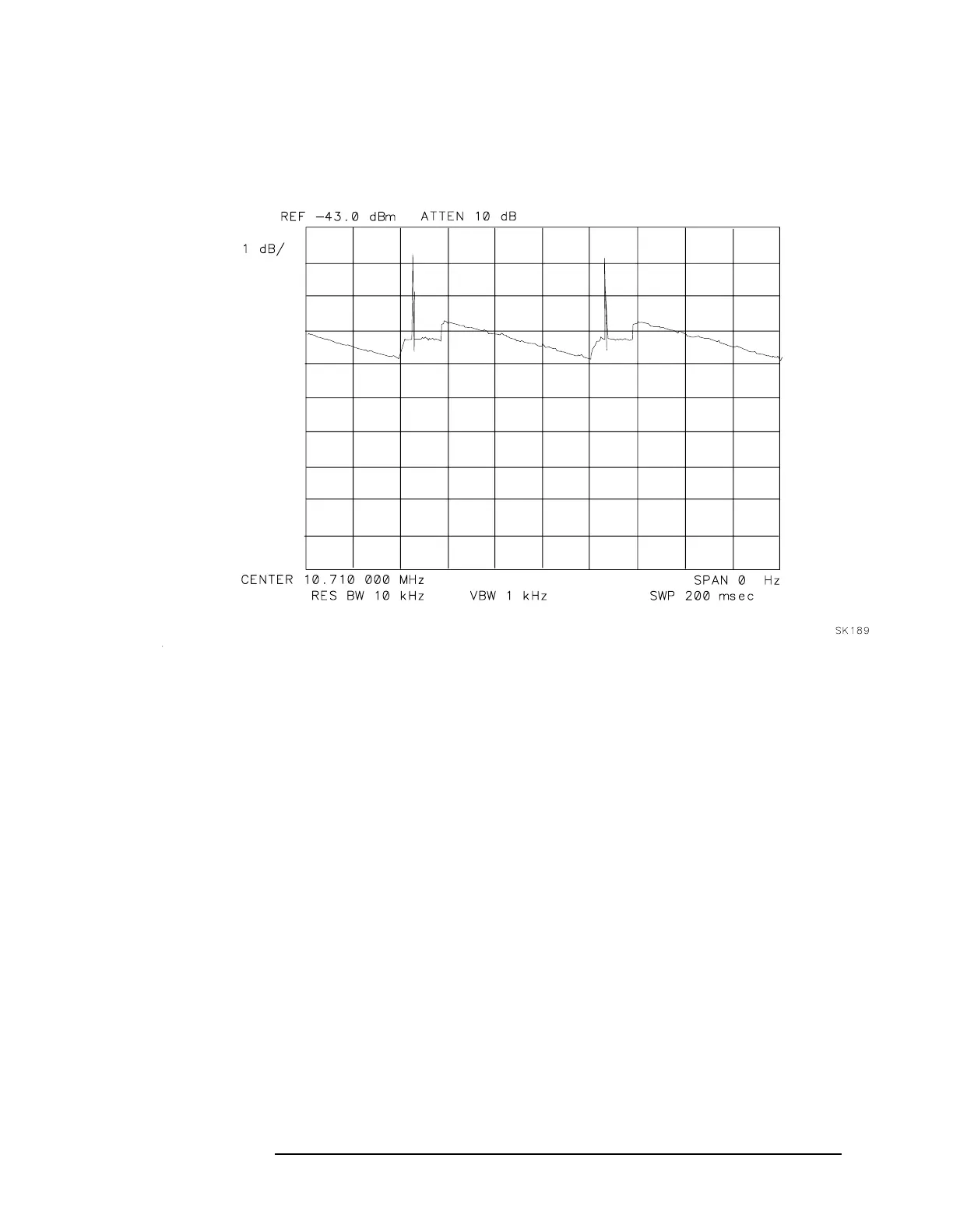
Figure 8-20 Failed Crystal Set Symptoms
Low-Pass Filter
Refer to function block AB of A4 Log Amplifier Schematic Diagram in
the
HP 8560 E-Series Spectrum Analyzer Component Level Information.
1. Connect a DVM positive probe to A4J9 pin 4.
2. On the spectrum analyzer, press
CAL.
3. Press
FULL IF ADJUST. Observe the DVM reading between the
displayed messages IF ADJUST STATUS: 300 kHz RBW and IF
ADJUST STATUS: 3 kHz RBW. During this time period, the voltage
should be within a 2 to 10 Vdc range.
4. Observe the DVM reading while IF ADJUST STATUS: AMPLITUDE is
displayed. The reading should be within the 2 to 10 Vdc range.
5. If the DVM reading is outside the range in step 3 but inside the
range in step 4, suspect a reactive component in the filter.