The types of signals that can be measured using the time gate function include:
n Pulsed RF signals
n Time domain multiple access (TDMA) communication system signals
n Interleaved or intermittent signals
n Signals with transient spectra
Time critical signals are present in many different applications. A few of the applications are
listed below:
n Digital cellular communication systems require measurements on pulse modulated TDMA
signals. Measurements must be accurately aligned with the time division multiple access
(TDMA) burst of the communication carrier. The time gate can position spectrum analyzer
measurement to assess TDMA burst timing and the quality of the burst modulation.
n Rotating head devices, such as VCRs and hard disks, have time interleaved signals
multiplexed from alternate recording tracks on the storage media. The time gate can isolate
the spectrum due to a single recording track.
n Tests required for mobile communication systems often require that the transient spectrum,
due to pulse modulation, be excluded from measurement results.
Example: Measure a Pulsed RF signal.
1. The rear panel GATE OUTPUT must be connected to EXT TRIG INPUT.
2. A TTL trigger signal must be connected to GATE TRIGGER INPUT on the rear panel. If no
trigger is present an error message is displayed and the gate utility will not be activated.
3. Press
[PRESET].
Connect a pulsed RF signal to the spectrum analyzer INPUT 503.
4. Press
(FREQUENCY)
and enter the frequency of your input signal to place the signal at the
spectrum analyzer center frequency.
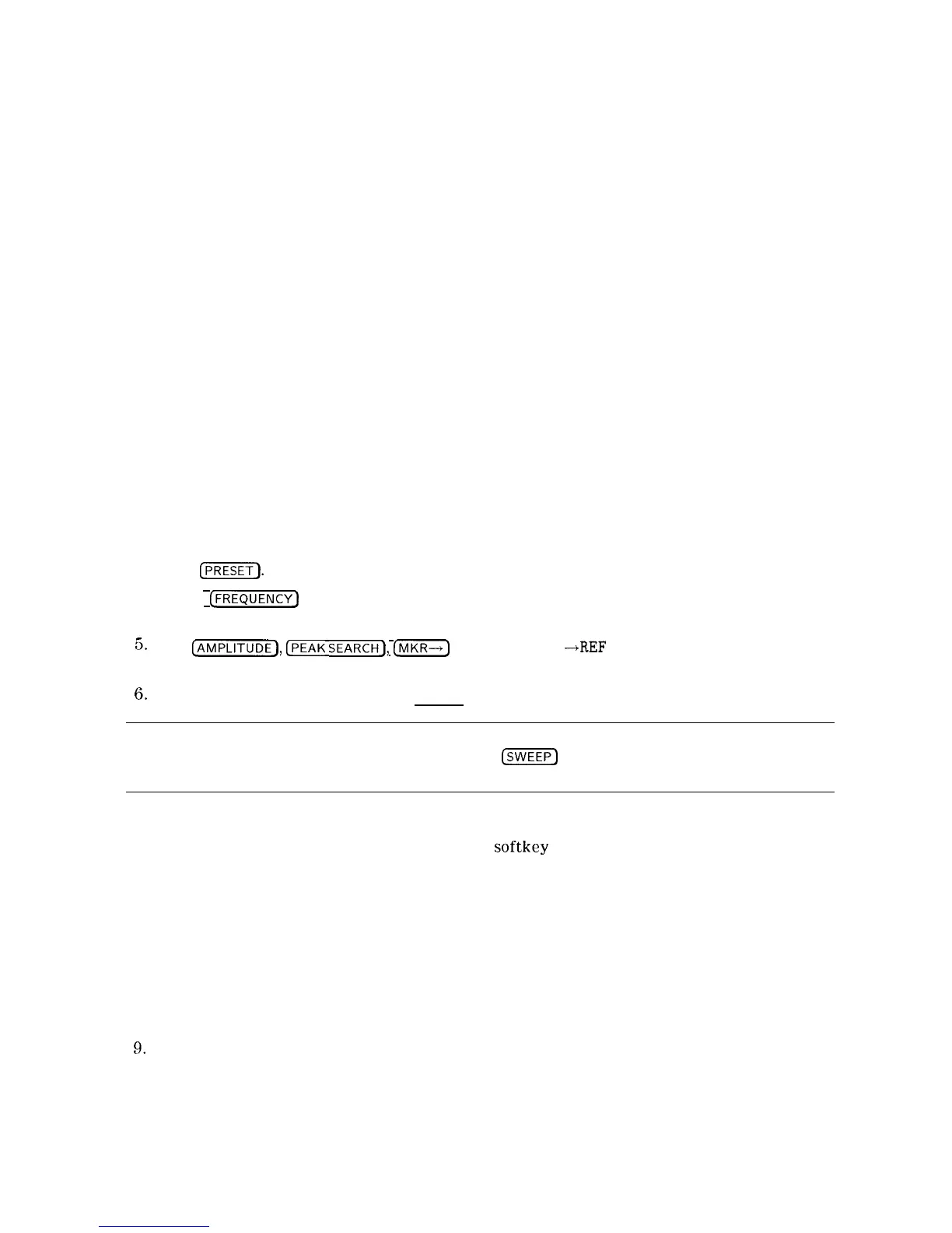
5.
Press
@iEiTEFj,
CPEAK
SEARCH),
[MKR--I)
and MARKER
-+REF
LVL to bring the signal to the
top of the display.
6.
Access the gate utility by pressing [SWEEP], Gate Control , and GATE UTILITY .
Note
If the gate menus are exited without turning the gate utility off (by pressing
another front panel key), press the
(-1
key twice to return to the last gate
utility menu used.
7. Press Define Time to set up the time domain window (the upper window.) Change the
sweep time using the T WINDOW SWP TIME
softkey
so that the pulses are displayed. Press
SWEEP DELAY and use the knob to center the pulses in the upper window.
8. The trigger marker reads out the time from the rear panel gate trigger point to the current
marker position. Turn the trigger marker on by pressing TRIG MKR ON OFF (ON) and
use the knob to move the trigger marker to the edge of the pulse. The marker readout
indicates the position of the edge relative to the rear panel trigger. The trigger marker may
be used to perform “settling time” measurements on the rising or falling edges of a digital
communications signal. (Settling time is the time from the trigger to 90 percent of the
stable pulse on/off value.)
9.
Press Main Menu to exit the define time menu.
4-20 Making Measurements