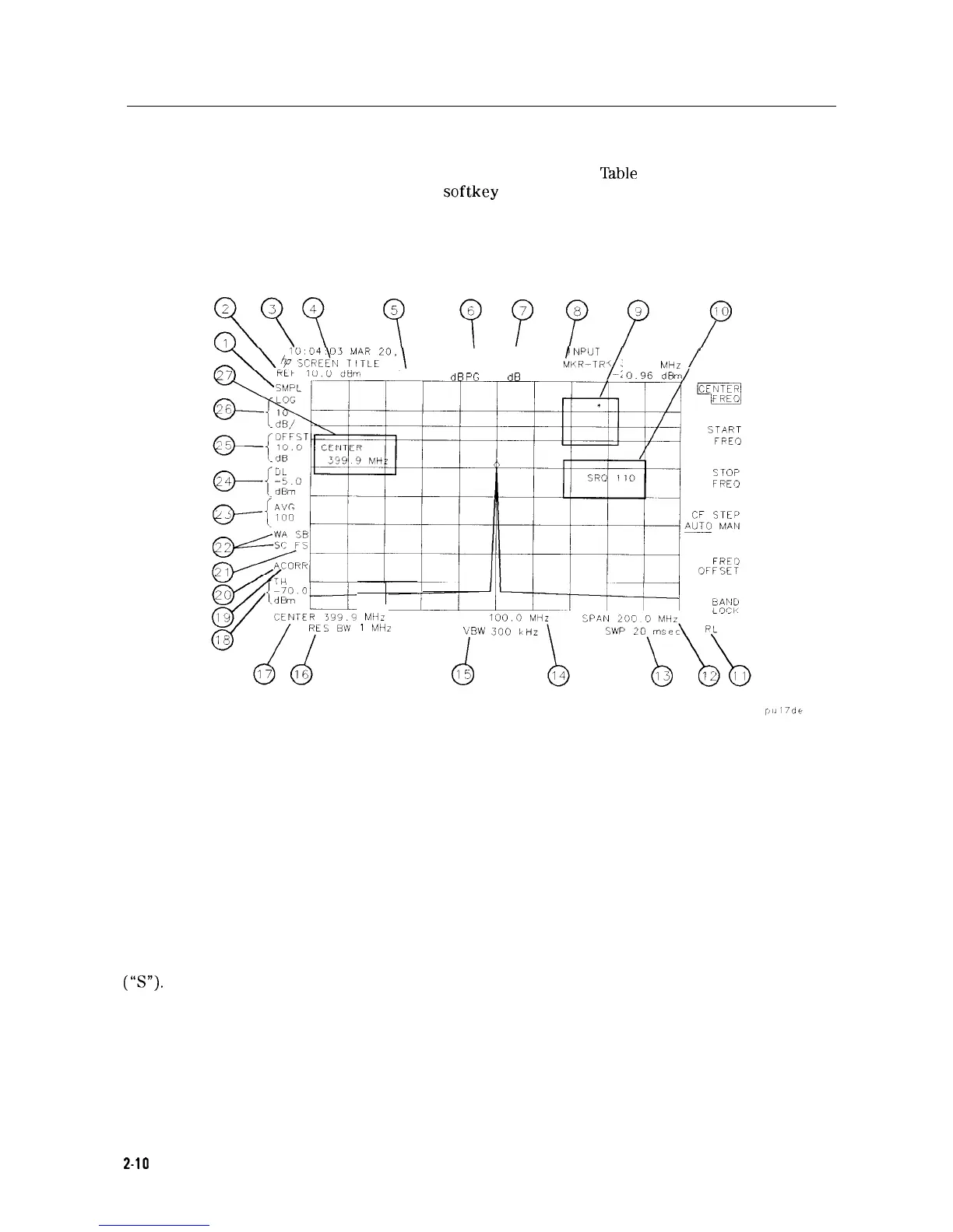
Screen Annotation
Figure 2-4 shows an example of the annotation that may appear on a spectrum analyzer screen.
The screen annotation is referenced by numbers and is listed in
‘Iable
2-2. The function key
column indicates which front-panel key or
softkey
activates the function related to the screen
annotation. Refer to Chapter 7 for more information on a specific function key.
1989 EXTE4 NAL
KEYBOARD
ENPUT
MIIR-TKK
399.9
/
MHz
/
AT 20
dB
PG
10.0
dB
-2
MHz
I
MHz
OFFST
VIYW
d
15
Figure 2-4. Screen Annotation
In Figure 2-4, item 21 refers to the trigger and sweep modes of the spectrum analyzer. The first
letter (“F”) indicates the spectrum analyzer is in free-run trigger mode. The second letter (“S”)
indicates the spectrum analyzer is in single-sweep mode.
Item 22 refers to the trace modes of the spectrum analyzer. The first letter (“W”) indicates that
the spectrum analyzer is in clear-write mode. The second letter is “A,” representing trace A.
The trace B trace mode is “SB”, indicating trace B (“B”) is in the store-blank mode (“S”). The
trace mode annotation for trace C is displayed under the trace mode annotation of trace A. In
Figure 2-4, the trace C trace mode is “SC”, indicating trace C (“C”) is in the store blank mode
(‘is’).
Refer to Table 2-3 for the screen annotation codes for trace, trigger, and sweep modes.
The WINDOWS display mode splits the screen into two separate displays. Only one of these
displays is active at a time. The currently active window will have a solid line around the
graticule rather than a broken line. The complete annotation is not available for each window
because of space limitations.
2-10
Getting Started