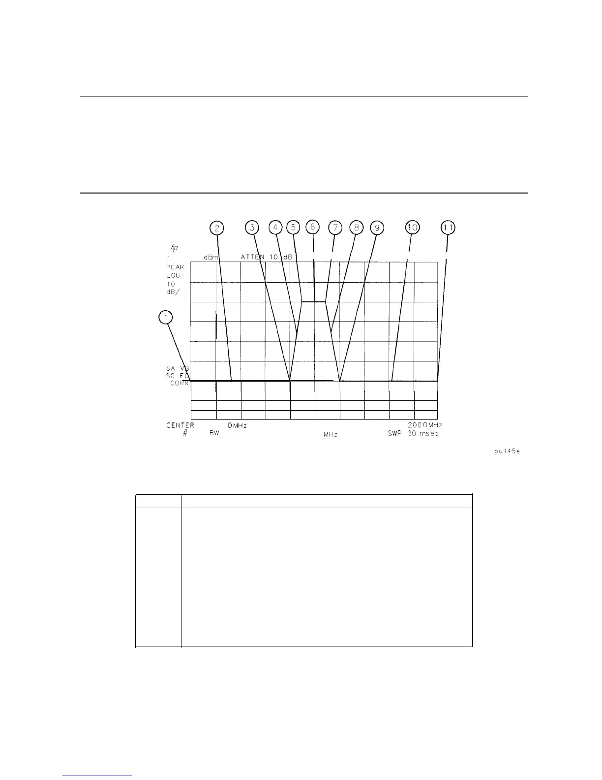
segment. Limit lines are constructed from left to right. The segment is defined by its beginning
point (see Figure 5-6).
Note
Up to 20 segments can be specified for an upper or lower limit-line table.
When entering a limit-line segment, the frequency/time and amplitude values
will be listed as asterisks (***) until new values are entered. The new segment
will be listed last until both the frequency (or time) and the amplitude values
have been entered. Once the frequency/time and an amplitude value are
entered, the segment will be sorted into the limit-line table according to
frequency or time.
(-3
yyyfppp
p
y
4
REF .O
dBm
ATT&
lO\dB
I I
I
I
I
I
CENTEP
300
MHz
#
B’N
VBW 1
MHz
SPAN
ZOO
0
MH7
SWP
:
!O
msec
Figure 5-6. Limit-Line Segments
Item
Description of Items in Figure 5-6
1
Frequency and amplitude coordinate that starts the first segment.
2
First segment.
3
Frequency and amplitude coordinate that starts the second segment.
4
Second segment.
5
Frequency and amplitude coordinate that starts the third segment.
6
Third segment.
7
Frequency and amplitude coordinate that starts the fourth segment.
8
Fourth segment.
9
Frequency and amplitude coordinate that starts the fifth segment.
10
Fifth segment.
11
Frequency and amplitude coordinate that starts the sixth segment.
5-24 Using Analyzer Features