EasyManuals Logo

HP A5120 EI Series Installation Guide

HP A5120 EI Series
91 pages
To Next Page IconTo Next Page
To Previous Page IconTo Previous Page
Page #11 background imageLoading...
Page #11 background image
6
Mounting bracket views
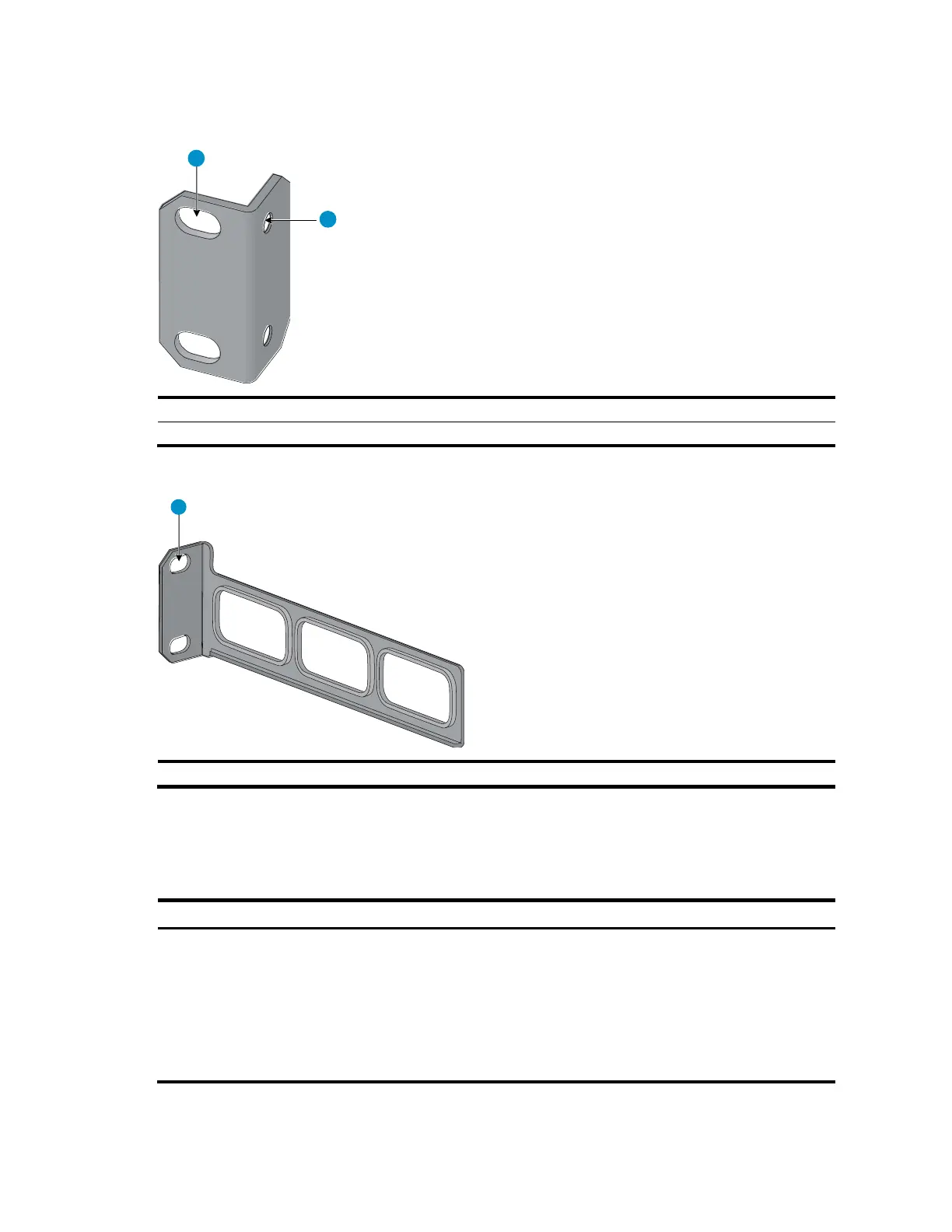
Figure 2 Front mounting bracket
1
2
(1) Hole for attaching to a rack (by using an M6 screw)
(2) Hole for attaching to the switch chassis
Figure 3 Rear mounting bracket
1
(1) Hole for attaching to a rack (by using an M6 screw)
Mounting brackets shipped with different switch models
Table 7 shows the mounting brackets included with different switch models.
Table 7 Mounting bracket kit shipped with the A5120 EI switches
Chassis
Front mounting brackets
Rear mounting brackets
A5120-24G EI (2 slots)
A5120-24G EI TAA (2 slots)
A5120-48G EI (2 slots)
A5120-48G EI TAA (2 slots)
A5120-24G EI
A5120-48G EI
One pair
N/A

Table of Contents

Other manuals for HP A5120 EI Series

Questions and Answers:

Question and Answer IconNeed help?

Do you have a question about the HP A5120 EI Series and is the answer not in the manual?

HP A5120 EI Series Specifications

General IconGeneral
Uplink Ports4 x SFP
StackingNo
ManagementCLI, Web, SNMP
Routing ProtocolsRIP, OSPF
Power SupplyAC
MAC Address Table Size16K
Dimensions440 x 430 x 44 mm
Operating Temperature0°C to 45°C
Operating Humidity10% to 90% non-condensing
ModelHP A5120-24G EI Switch (JG234A)
VLANs4094

Related product manuals