Power switch
The power switch is attached to the left, front of the chassis.
1. Prepare the computer for disassembly (
Preparation for disassembly on page 66).
2. Remove the access panel (
Access panel on page 67).
3. Remove the front bezel (
Front bezel on page 67).
4. Rotate the drive cage to its upright position.
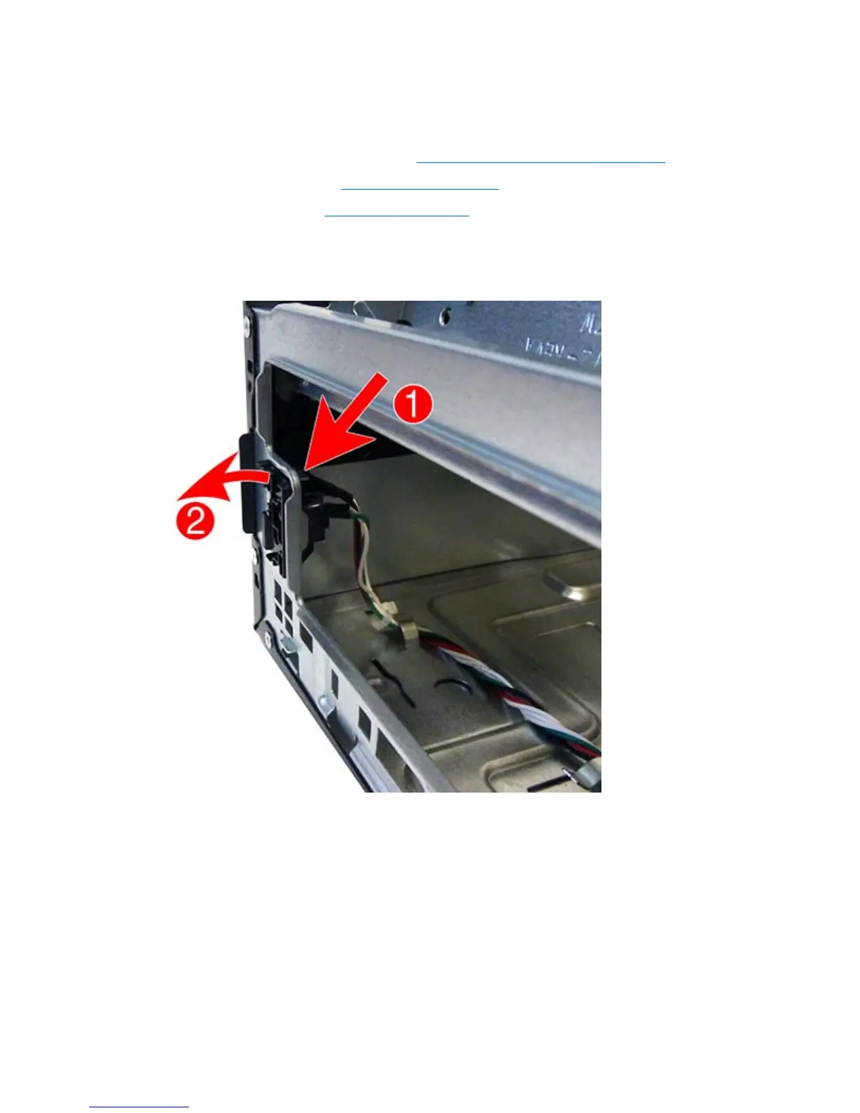
5. From the inside of the front of the chassis, press the tab at the top of the power switch (1) and
push the top of the power switch away from the front of the chassis (2).
6. Remove the cable from the clips built into the bottom of the chassis (1).
98 Chapter 6 Removal and replacement procedures – small form factor (SFF) chassis
 Loading...