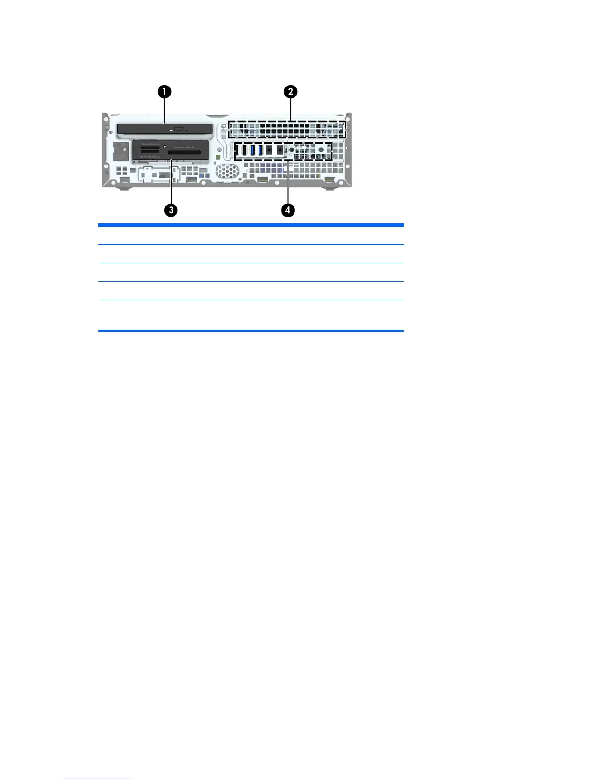
Drive positions
1 Slim optical drive bay
2 3.5-inch internal hard drive bay
3 3.5-inch drive bay for optional drives (media card reader shown)
4 2.5-inch internal hard drive bay
NOTE: The drive configuration on your computer may be different than the drive
configuration shown above.
To verify the type and size of the storage devices installed in the computer, run Computer Setup.
Installing and Removing Drives
When installing drives, follow these guidelines:
●
The primary Serial ATA (SATA) hard drive must be connected to the dark blue primary SATA
connector on the system board labeled SATA0.
●
Connect secondary hard drives and optical drives to one of the light blue SATA connectors on
the system board (labeled SATA1 and SATA2).
●
Connect a media card reader USB 2.0 cable to the USB connector on the system board labeled
MEDIA.
●
The power cable for the drives has two branches coming off the system board connector. The
first branch is a dual-headed cable with the first connector (four-wire) routed to the 3.5-inch
optional drive bay and the second connector (two-wire) routed to the slim optical drive bay. The
second branch is a dual-headed cable with the first connector routed to the 3.5-inch hard drive
bay and the second connector routed to the 2.5-inch hard drive bay.
78 Chapter 6 Removal and replacement procedures – small form factor (SFF) chassis
 Loading...