6. Rotate the assembly into the chassis (1).
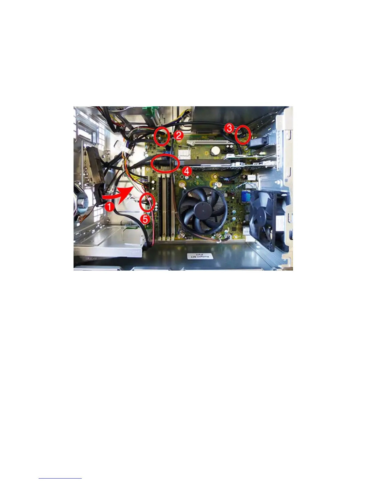
7. Disconnect the four cables from the following system board connectors:
(2): Front USB (yellow)
(3): Front AUD (blue)
(4): Front USB3.0 (blue)
(5): PB/LED (black)
8. Remove the assembly from the inside of the computer.
To reinstall the assembly, reverse the removal procedure.
54 Chapter 5 Removal and replacement procedures – Microtower (MT) chassis
 Loading...