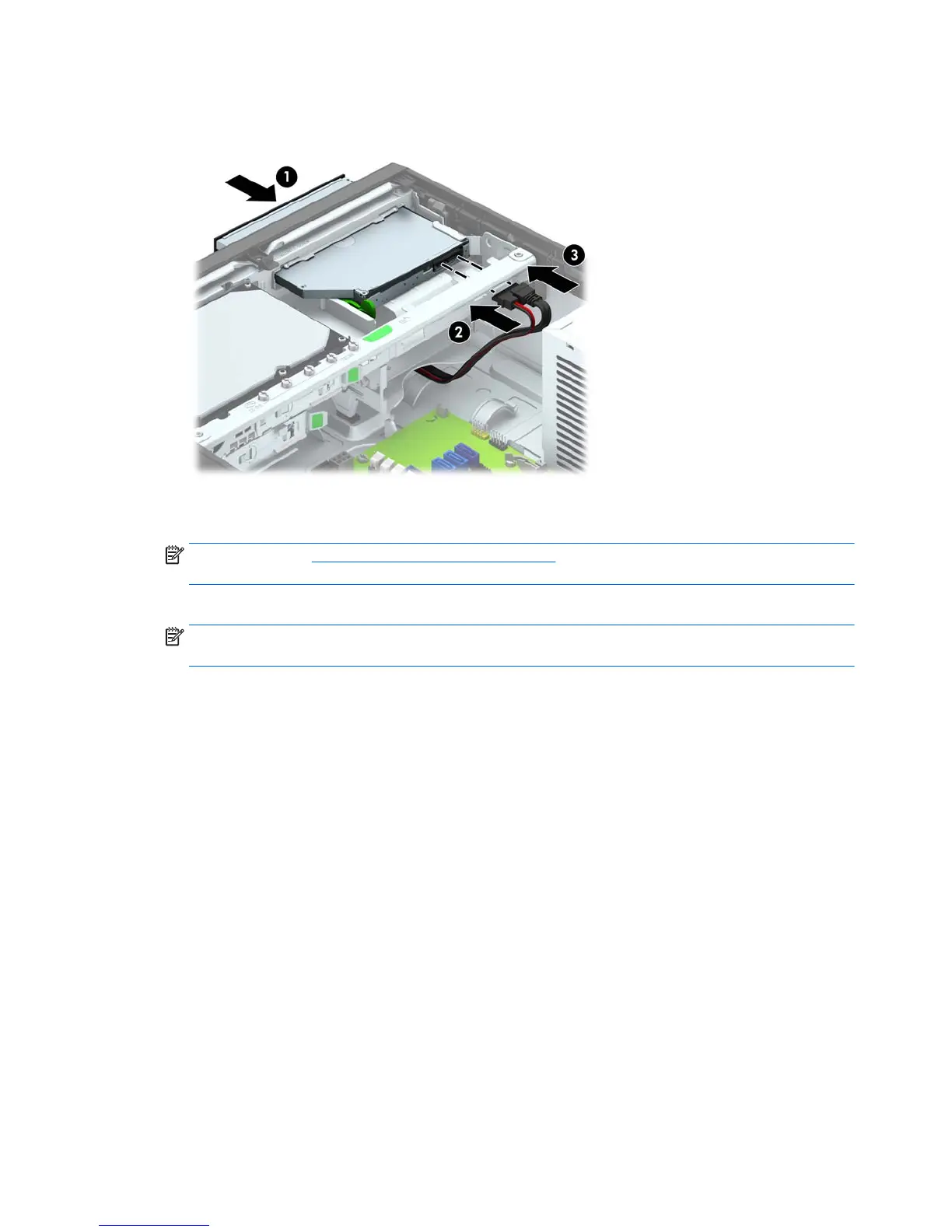
5. Slide the optical drive through the front bezel all the way into the bay so that it locks in place (1),
then connect the power cable (2) and data cable (3) to the rear of the drive.
6. Connect the opposite end of the data cable to one of the light blue SATA connectors on the
system board.
NOTE: Refer to System board callouts on page 110 for an illustration of the system board
drive connectors.
7. Replace the front bezel if it was removed.
NOTE: An optional bezel trim piece that surrounds the front of the optical drive is available
from HP. Install the bezel trim piece in the front bezel before installing the front bezel.
8. Replace the computer access panel.
9. If the computer was on a stand, replace the stand.
10. Reconnect the power cord and any external devices, then turn on the computer.
11. Lock any security devices that were disengaged when the access panel was removed.
86 Chapter 6 Removal and replacement procedures – small form factor (SFF) chassis
 Loading...