Component identification 12
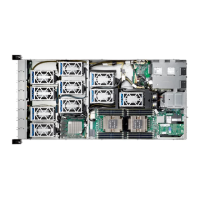
Slimline SAS connector #0 (SATA0)
Slimline sSAS connector #0 (SSATA0)
Front panel USB 3.0 connector
BMC firmware readiness LED
OCP mezzanine connector #1
sSATA connector #5 (for rear HDD)
sSATA connector #4 (for rear HDD)
VROC upgrade module (optional)
Power Supply Unit connector 2 (secondary)
Power Supply Unit connector 1 (primary)
Slimline SAS connector #1 (SATA1)
Rear back plane board power connector
HDD back plane board power connector
Extension card power connectors (3)
Processor 1 DIMM slots (6)
Processor 1 DIMM slots (6)
Processor 0 DIMM slots (6)
* The table below describes the type of connections enabled for various LAN combinations as determined
by the NCSI switch
Both, with dedicated LAN as the first priority
Both, with dedicated LAN as the first priority
Dedicated LAN and OCP card only, with dedicated
LAN as the first priority

 Loading...
