Component identification 9
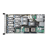
Rear panel identification
PCIe add-on card slot 8 (Processor 1)
PCIe add-on card slot 7 (Processor 1)
PCIe add-on card slot 6 (Processor 1)
PCIe add-on card slot 5 (Processor 1)
PCIe add-on card slot 4 (Processor 0)
PCIe add-on card slot 3 (Processor 0)
PCIe add-on card slot 2 (Processor 0)
PCIe add-on card slot 1 (Processor 0)
Serial port
(if DB9 connector interface is required, an RJ-45 to DB9 cable is
needed)
NOTE: *See “Rear panel LED indicators” on page 19 for descriptions of LEDs.
NOTE: **Sequence is from top to bottom
BIOS PCIe Slot Number Mapping
The following table and image describes how each PCIe slot is defined in BIOS:
PCIe Slot 1 (Processor 0)
PCIe slot 1 (Processor 0)
PCIe Slot 2 (Processor 0)
PCIe slot 3C (Processor 0)
PCIe Slot 3 (Processor 0)
PCIe slot 3 (Processor 0)

 Loading...