94
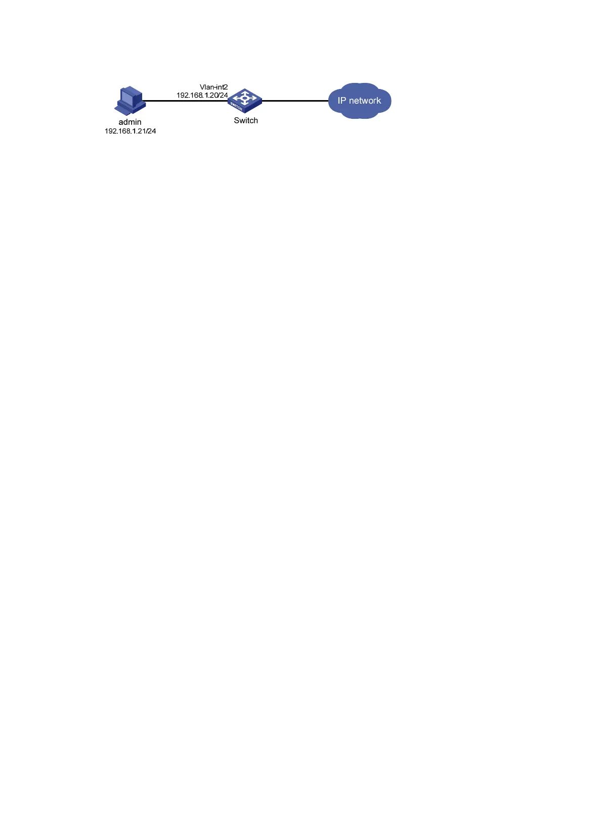
Figure 13 Network diagram
Configuration procedure
1. Configure the VLAN and VLAN interface:
a. From the navigation tree, select Network > Links > VLAN.
b. Create VLAN 2.
c. Access the details page for VLAN 2 to perform the following tasks:
− Add the interface that connects to the admin's PC to the tagged port list.
− Create VLAN-interface 2.
− Assign the IP address 192.168.1.20/24 to VLAN-interface 2.
2. Configure an administrator account:
a. From the navigation tree, select Device > Maintenance > Administrators.
b. Create an administrator account:
− Set the username and the password.
− Select the network-admin user role.
− Select HTTP as the permitted access type.
3. Enable the HTTP and HTTPS services:
a. From the navigation tree, select Network > Service > HTTP/HTTPS.
b. Enable the HTTP service.
c. Enable the HTTPS service.
Verifying the configuration
1. Verify that the administrator account is successfully added. (Details not shown.)
2. Enter http://192.168.1.20 in the address bar to verify the following items:
{ You can use the administrator account to log in to the Web interface.
{ After login, you can configure the device.
Stack configuration example
Network requirements
As shown in Figure 14, combine Switch A and Switch B into a virtual stack.
• Connect ports XGE 1/0/49 and XGE 1/0/50 on Switch A to ports XGE 1/0/49 and XGE 1/0/50 on
Switch B to create stack links.
• Use Switch A as the master.

 Loading...


