107
a. From the navigation tree, select Network > IP > DNS.
b. Configure the IP address of the DNS server as 2.1.1.2.
c. On the advanced settings page, configure the domain name suffix as com.
Verifying the configuration
# Use the ping host command on the switch to verify the following items:
• The ping operation succeeds.
• The switch can resolve the domain name host.com into the IP address 3.1.1.1.
DDNS configuration example with www.3322.org
Network requirements
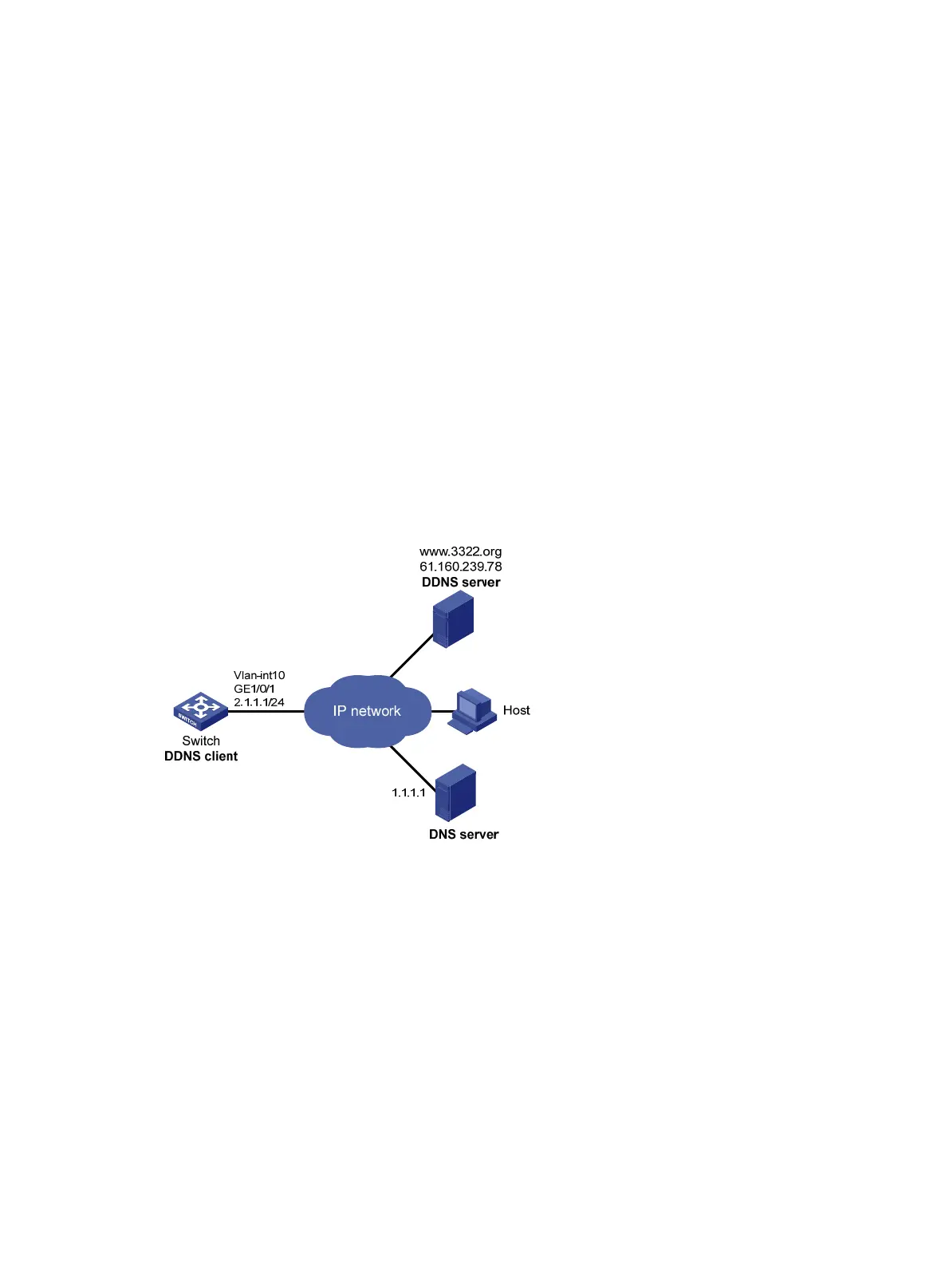
As shown in Figure 28, the switch is a Web server with the domain name whatever.3322.org.
• Configure a DDNS policy on the switch. The switch can then update its domain name-IP
address mapping on the DDNS server, and the DDNS server can update the mapping on the
DNS server.
• Configure DNS on the switch so that the switch can resolve www.3322.org into the IP address
61.160.239.78.
Figure 28 Network diagram
Configuration procedure
1. On the DDNS server, create an account:
Access the website at http://www.3322.org, and set the account name to abc and the
password to 123. (Details not shown.)
2. On the DNS server, create the mappings between domain names and IP addresses:
Create a mapping between 3322.org and 61.160.239.18, and a mapping between
whatever.3322.org and 2.1.1.1. (Details not shown.)
3. Configure network routes:
Configure static routes or dynamic routing protocols on each device to make sure the devices
can reach each other. (Details not shown.)
4. On the switch, configure the VLAN and VLAN interface:
a. From the navigation tree, select Network > Links > VLAN.
b. Create VLAN 10.

 Loading...


