103
Verifying the configuration
# Verify that the port roles and port states in the spanning tree status are as expected. (Details not
shown.)
LLDP configuration example
Network requirements
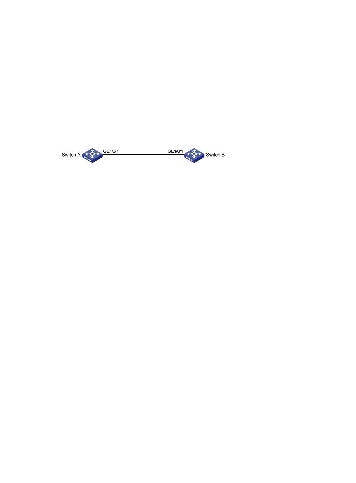
As shown in Figure 23, configure LLDP on Switch A and Switch B to meet the following
requirements:
• Switch A can discover Switch B and obtain system and configuration information from Switch B.
• Switch B cannot discover Switch A.
Figure 23 Network diagram
Configuration procedure
1. Configure LLDP on switch A:
a. From the navigation tree, select Network > Links > LLDP.
b. Enable LLDP globally.
c. Access the interface status page, and enable LLDP on GigabitEthernet 1/0/1.
d. Access the interface configuration page of advanced settings to perform the following tasks:
− Enable the nearest bridge agent function on GigabitEthernet 1/0/1.
− Configure the interface to only receive LLDP frames.
Then, Switch A can discover neighbors.
2. Configure LLDP on Switch B:
a. From the navigation tree, select Network > Links > LLDP.
b. Enable LLDP globally on Switch B.
c. Access the interface status page, and enable LLDP on GigabitEthernet 1/0/1.
d. Access interface configuration page of advanced settings to perform the following tasks:
− Enable the nearest bridge agent function on GigabitEthernet 1/0/1.
− Configure the interface to only transmit LLDP frames.
Then, Switch B cannot discover neighbors.
Verifying the configuration
1. Verify that you can see information about Switch B on the LLDP neighbor information page of
Switch A. (Details not shown.)
2. Verify that the LLDP neighbor information page of Switch B does not contain an entry for Switch
A. (Details not shown.)
DHCP snooping configuration example
Network requirements
As shown in Figure 24, configure DHCP snooping on Switch B to meet the following requirements:
• Allow only the interface that connects to the authorized DHCP server, GigabitEthernet 1/0/1 on
Switch B, can forward packets from the DHCP server.

 Loading...


