101
b. Access the advanced settings page, and set the mode to security.
c. Access the page for adding an OUI address, and add the OUI address 0011-2200-0000, the
mask ffff-ff00-0000, and the description OUI address of IP phone A.
Verifying the configuration
1. View the OUI summary to verify that the OUI address 0011-2200-0000 has been added.
2. View the port summary to verify that GigabitEthernet 1/0/1 has been assigned to voice VLAN 2.
MAC address entry configuration example
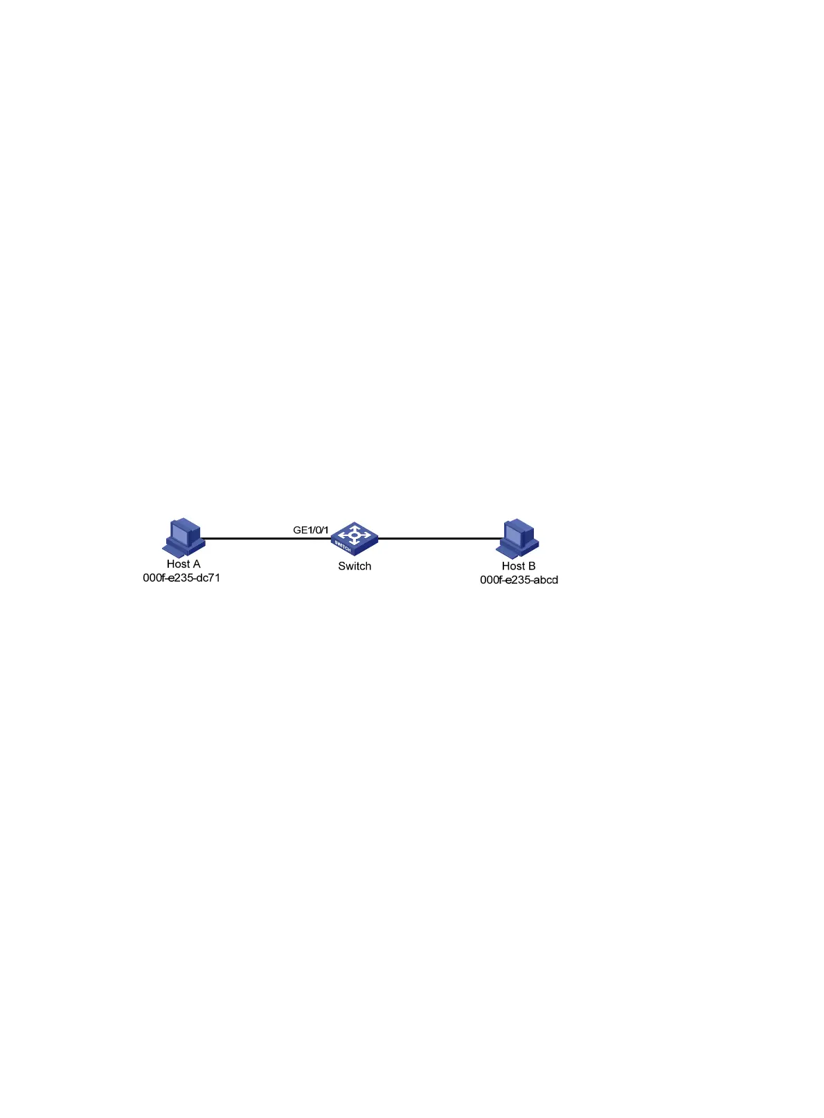
Network requirements
As shown in Figure 21:
• Host A at MAC address 000f-e235-dc71 is connected to GigabitEthernet 1/0/1 of the switch and
belongs to VLAN 1.
• Host B at MAC address 000f-e235-abcd, which behaved suspiciously on the network, also
belongs to VLAN 1.
Configure the MAC address table on the switch as follows:
• To prevent MAC address spoofing, add a static entry for Host A.
• To drop all frames destined for Host B, add a blackhole MAC address entry for Host B.
• Set the aging timer to 500 seconds for dynamic MAC address entries.
Figure 21 Network diagram
Configuration procedure
1. From the navigation tree, select Network > Links > MAC.
2. Add a static MAC address entry for the MAC address 000f-e235-dc71. The outgoing interface is
GigabitEthernet 1/0/1, and the VLAN is 1.
3. Add a blackhole MAC address entry for the MAC address 000f-e235-abcd. The VLAN is 1.
4. Access the MAC advanced settings page, and then set the MAC aging timer to 500 seconds.
Verifying the configuration
# Verify that the created MAC address entries exist in the MAC address table, and Host B cannot
ping Host A. (Details not shown.)
MSTP configuration example
Network requirements
As shown in Figure 22, all devices in the network are in the same MST region. Switch A and Switch B
work at the aggregation layer. Switch C and Switch D work at the access layer.
Configure MSTP so that packets from different VLANs are forwarded along different spanning trees.
• Packets from VLAN 10 are forwarded along MSTI 1.
• Packets from VLAN 30 are forwarded along MSTI 2.

 Loading...


