98
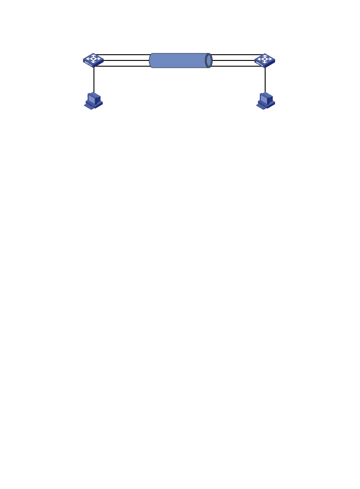
Figure 17 Network diagram
Configuration procedure
1. Configure Ethernet link aggregation on Switch A:
a. From the navigation tree, select Network > Interfaces > Link Aggregation.
b. Configure a Layer 2 aggregation group on Switch A as follows:
− Configure the aggregation mode as static.
− Assign ports to the aggregation group.
2. Configure the VLAN on Switch A.
a. From the navigation tree, select Network > Links > VLAN.
b. Create VLAN 10.
c. Access the details page for VLAN 10 to perform the following tasks:
− Add the port that connects to Host A to the untagged port list.
− Add ports GigabitEthernet 1/0/1 through GigabitEthernet 1/0/3 to the tagged port list.
3. Configure Switch B in the same way Switch A is configured. (Details not shown.)
Verifying the configuration
1. Access the link aggregation page, and verify that ports GigabitEthernet 1/0/1 through
GigabitEthernet 1/0/3 have been assigned to the link aggregation group. (Details not shown.)
2. Verify that Host A can ping Host B. (Details not shown.)
3. Verify that Host A can still ping Host B after a link between Switch A and Switch B fails. (Details
not shown.)
Port isolation configuration example
Network requirements
As shown in Figure 18, configure the switch to provide Internet access for all the hosts and isolate
them from one another.
Link aggregation 10
Switch A Switch B
GE1/0/1
GE1/0/3
GE1/0/2 GE1/0/2
GE1/0/3
GE1/0/1
Host A
VLAN 10 VLAN 10
Host B
GE1/0/4 GE1/0/4

 Loading...


