Shenzhen Hpmont Technology Co., Ltd Chapter 6 Function Introduction
HD20 Series Inverters User Manual ―85―
No. Name Description Range
factory setting
13: Limitation of lower limit of frequency. The indicating signal will be output if the setting frequency is
lower than the lower limit of frequency.
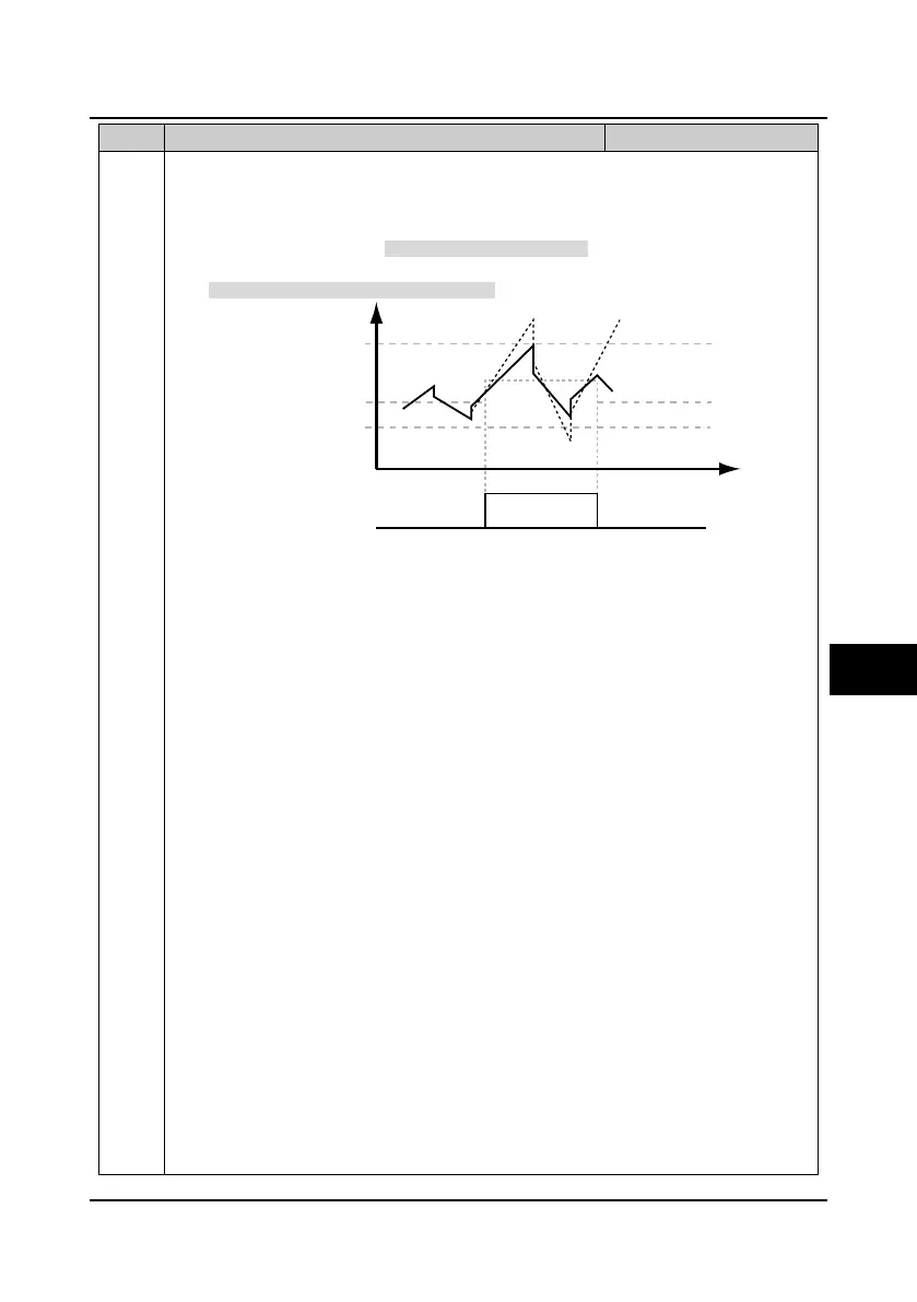
14: Limitation of upper/lower limits of wobble frequency.
• If the wobble frequency calculated by the central frequency is higher than upper limit of
frequency or lower than the lower limit of frequency (F00.09), signal will be output, as shown in
figure.
• When F07.00 = 1 (using the wobble function), this terminal function is enabled.
15: Simple PLC operating status indication. The indicating signal will be output when the inverter is at
simple PLC operating.
16: Simple PLC pausing indication. The indicating signal will be output if the simple PLC operation is
suspended by external terminals.
17: Simple PLC cycle completion indication. The indicating signal will be output if one cycle of PLC
operation is finished.
18: Completion of simple PLC operation stages. The indicating signal will be output if the current step
of PLC operation is finished.
19: Completion of simple PLC operation. The indicating signal will be output if the PLC operation is
finished.
20: Output data from SCI communication. Output indicating signal of open collector or relay is
controlled by the SCI communication directly.
21: Preset operating time out.
• The indicating signal will be output if the inverter’s operating time reaches the preset operating
time (F15.36)
Note: The No. 17, 18, 19 and 21 functions output indicating signal which is single pulse signal,
500ms.
22: Timing function output. If the setting is 22, the inverter can use the timing function output terminal.
• Refer to parameters F15.25 and F15.26.
23: Preset counting value reach.
24: Indicating counting value reach.
• Refer to parameters F15.37 and F15.38.
25: Setting length arrive. The indicating signal will be output if the inverter’s actual length reaches the
preset length.
26: Indication of motor 1 and motor 2. According to the current motor selection, output corresponding
indicating signal.
• When the inverter controls the motor 1, this signal will be disabled; while controls the motor 2, it
will output the indicating signal.
27,28: Reserved.
F00.09
Running frequency
Lower limit of frequency
Central frequency
Upper limit of frequency
Before limiting amplitude
After limiting amplitude
Wobble frequency
Time
Output signal
Limitation of upper/lower limits of wobble frequency
6
 Loading...


