Chapter 6 Function Introduction Shenzhen Hpmont Technology Co., Ltd
―88― HD20 Series Inverters User Manual
No. Name Description Range
factory setting
F15.33 FDT2 detection mode 0,1
0
0: Detect according to the reference frequency.
1: Detect according to the output frequency.
F15.34 FDT2 level 0.00
upper limit
50.00Hz
Refer to parameters F15.31 and F15.32.
When the total operating time reaches the preset operating time (F15.36), the inverter will output an
indicating signal (500ms).
Preset counting value arriving
F15.38 Specified counting value arriving 0
F15.37
0
F15.37 presents that when the number of pulse input by the multi-function input terminals (set as No.
51 function) reaches a certain quantity, the multi-function output terminals or relay will send an
indicating signal while the external counter will auto-clear too.
F15.38 presents that when the number of pulse input by the multi-function input terminals (set as No.
51 function) reaches a specified quantity, the multi-function output terminals or relay will send an
indicating signal until the pulse number hits the preset counting value.
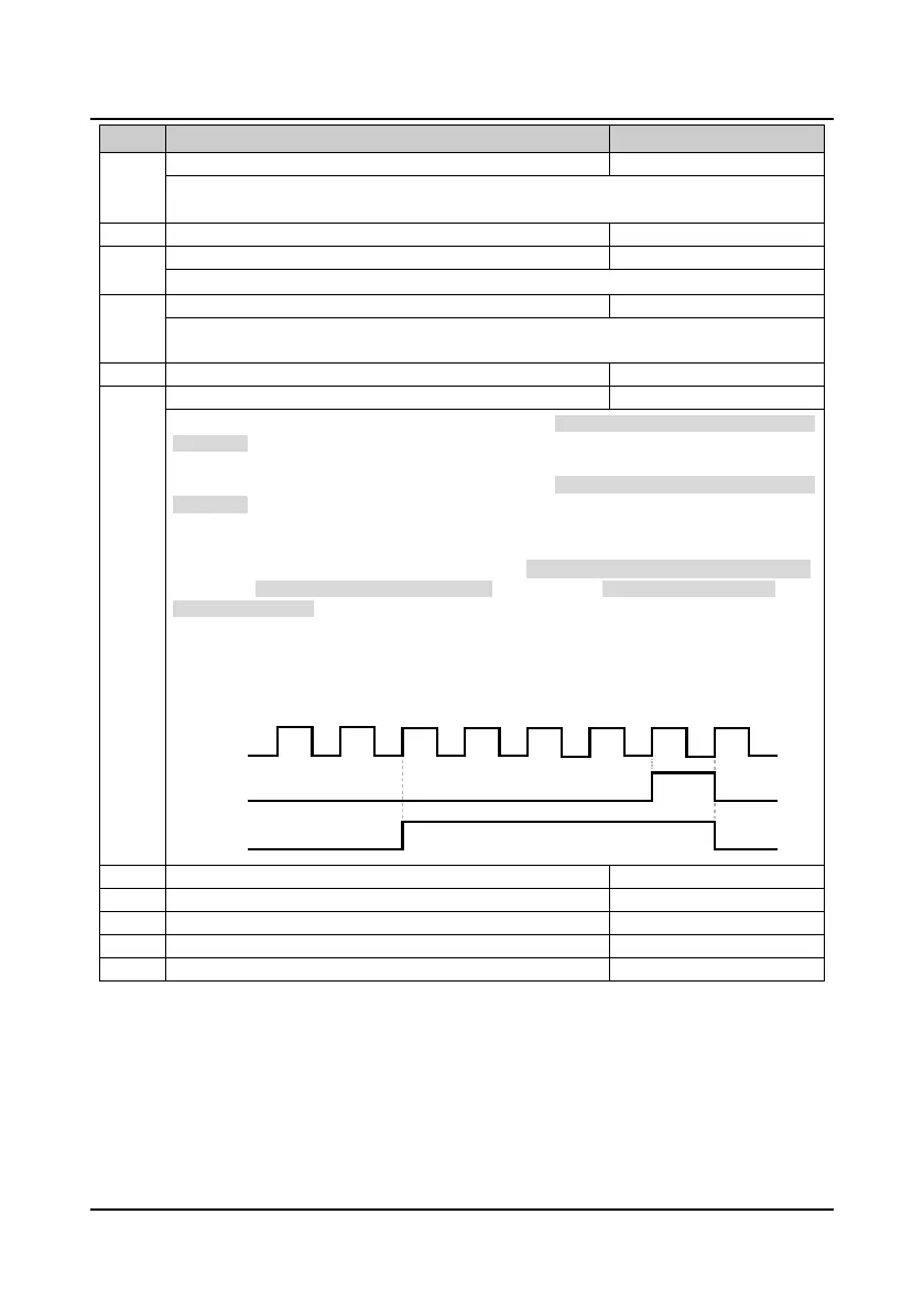
For instance:
If F15.37 is set to 7 and F15.38 is set to 3, DO1 selects preset count arriving function (F15.18 = 23),
DO2 selects specified count arriving (F15.19 = 24), and DI1 selects counter trigger signal input
function (F15.00 = 51).
Sequence of counting value arriving is shown in figure:
• DO2 will output an indicating signal when DI1 inputs the third pulse until the preset count value
reachs seven.
• DO1 will output an indicating signal when DI1 inputs the seventh pulse; output signal of DO1
returns to low level when DI1 inputs the eighth pulse.
F15.40 Reserved
F15.42 Reserved

 Loading...

