Shenzhen Hpmont Technology Co., Ltd Chapter 6 Function Introduction
HD20 Series Inverters User Manual ―87―
No. Name Description Range
factory setting
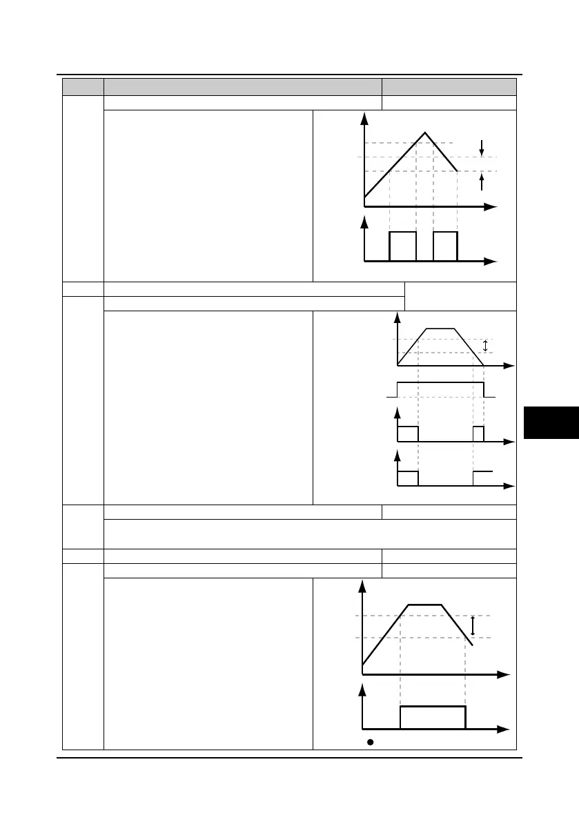
F15.27 FAR range 0.00
100.00
2.50Hz
The pulse signal will be output if the inverter’s
output frequency is within the FAR range. As
shown in the right figure.
F15.28 Zero-frequency operation threshold 0.00
upper limit
0.00Hz
Zero-frequency hysteresis
F15.28 and F15.29 are used to set the
zero-frequency operation output control function,
please see the right figure.
0: Detect according to the reference frequency.
1: Detect according to the output frequency.
0.00-upper limit【50.00Hz】
F15.32 FDT1 lag 0.00
upper limit
1.00Hz
The indicating signal can be output if the setting
frequency F15.30 is higher than certain frequency
(F15.31), and becomes disabled when the setting
frequency is lower than certain frequency of FDT1
level (F15.31 - F15.32). Please refer to FL of the
right figure.
Output
Detecting range
Preset
frequency
Time
Time
DO
Running status
Running frequency
F15.29
F15.28
Zero-frequency output
Time
Time
Time
Zero-frequency
operation output
Output frequency
F15.32
F15.31
FL
DO
FL = F15.31 - F15.32
Time
Time
6
 Loading...


