Shenzhen Hpmont Technology Co., Ltd Appendix A Parameters
HD20 Series Inverters User Manual -139-
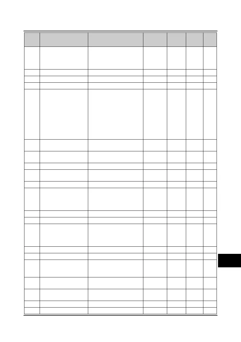
No. Name Range
Factory
Default
Unit
Modified
attributes
Setting
33: Inverter auto-reset fault
34-37: Reserved
38: High-frequency output
(only DO2)
F15.21 Reserved
F15.22 Reserved
F15.23 Reserved
F15.24
Output terminal positive
and negative logic
selection
Bit0-Bit2 is corresponding to
DO1-DO2
Bit2-Bit5 is corresponding to
RLY1-RLY4
Bitx: DOy and RLYy terminals
output positive and negative
logic
0 means positive logic
1 means negative logic
0 1 ○
F15.25
ON side delay time of
timing function
0.00-300.00s 0.00s 0.01s ○
F15.26
OFF side delay time of
timing function
0.00-300.00s 0.00s 0.01s ○
F15.27 FAR range 0.00-100.00Hz 2.50Hz 0.01Hz ○
F15.28
Zero-frequency operation
threshold
0.00-upper limit frequency 0.00Hz 0.01Hz ○
F15.29 Zero-frequency hysteresis 0.00-upper limit frequency 0.00Hz 0.01Hz ○
F15.30 FDT1 detection mode
0: Detect according to the
reference frequency
1: Detect according to the
output frequency
0 1 ○
F15.31 FDT1 level 0.00-upper limit frequency 50.00Hz 0.01Hz ○
F15.32 FDT1 lag 0.00-upper limit frequency 1.00Hz 0.01Hz ○
F15.33 FDT2 detection mode
0: Detect according to the
reference frequency
1: Detect according to the
output frequency
0 1 ○
F15.34 FDT2 level 0.00-F00.06 50.00Hz 0.01Hz ○
F15.35 FDT2 lag 0.00-F00.06 1.00Hz 0.01Hz ○
F15.36 Preset operating time
0-65535h
0: Preset operating time is
disabled
0h 1h ○
F15.37
Preset counting value
arriving
F15.38-9999 0 1 ○
F15.38
Specified counting value
arriving
0-F15.37 0 1 ○
F15.39 Reserved
F15.40 Reserved
A
 Loading...


