Chapter 4 Electrical Installation Shenzhen Hpmont Technology Co., Ltd
―26― HD20 Series Inverters User Manual
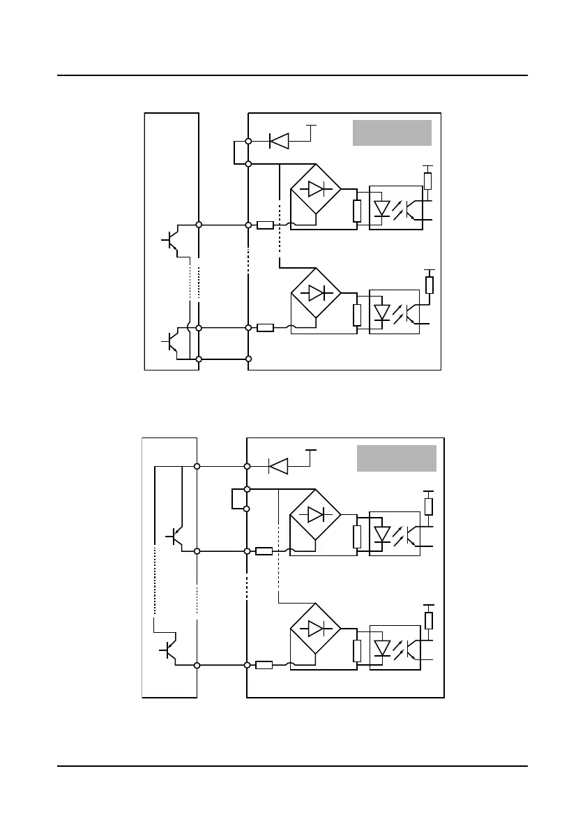
3. If the inverter’s internal 24V power supply is used, the common emitter output connection of
the NPN transistor in the external controller is as shown in Figure 4-11.
Figure 4-11 NPN signal input connection when using internal 24V power
4. If the inverter’s internal +24V power supply is used, the common emitter output connection of
the PNP transistor in the external controller is as shown in Figure 4-12. (Note that the SEL and
the P24 are not short-circuited)
Figure 4-12 PNP signal input connection when using internal 24V power
+ 3.3V
+
-
R
+ 24V
P24
SEL
DI1
+ 3.3V
+
-
COM
DI6
R
6
1
External
controller
NPN connection
using internal power
+ 3.3V
+
-
R
+ 24V
P24
SEL
DI1
+ 3.3V
+
-
COM
DI6
R
6
1
External
controller
PNP connection
using internal power
 Loading...


