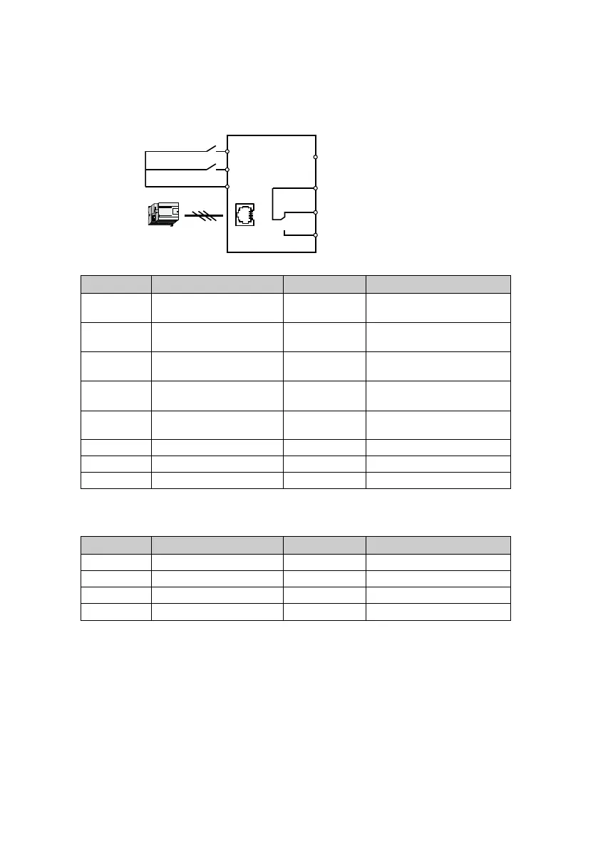
Control the start/stop via terminals and set the running frequency via communication
1. The terminal DI1 is forward running signal input, and DI2 is reverse running signal input, their
wirings are as following figure.
2. After power on, set the functional parameters in accordance with wirings, as following table.
No. Parameter name Setting value Meaning
F00.10
Frequency setting source
selection
2 SCI communication setting
F00.11
Command setting source
selection
1
Terminal running command
source
F15.00
DI1 terminal function
selection
2 (factory setting)
Forward running function
(terminal forward signal input)
F15.01
DI2 terminal function
selection
3 (factory setting)
Rervese running function
(terminal rervese signal input)
F15.18
DO1 terminal function
selection
2 (factory setting) Inverter is running
F17.00 Data format 0 (factory setting) 1-8-2 format, no parity, RTU
F17.01 Baud rate 3 (factory setting) 9600bps
F17.02 Local address 2 (factory setting)
3. Set motor parameters (see motor nameplate parameters) and acceleration/deceleration time
via the display panel, as following table.
No. Parameter name No. Parameter name
F08.00 Rated power of motor 1 F08.04 Rated RPM of motor 1
F08.01 Rated voltage of motor 1
F08.02 Rated current of motor 1 F03.01 Acceleration time 1
F08.03 Rated frequency of motor 1 F03.02 Deceleration time 1
4. Close the K1 of the wiring diagram, the motor will run forward; close K2, run reverse;
simultaneously close or disconnect, the motor will stop.
DI1
COM
K1
K2
Forward terminal
DI2
Reverse terminal
DO1
R1A
R1C
R1B
Fault indication normally closed contact
Output indicating signal at running
Fault indication normally open contact
Common terminal
1
2
34 5 6 7 8
RJ4 5
MODBUS
communication
SCI communication
terminal
 Loading...


