Chapter 6 Function Introduction Shenzhen Hpmont Technology Co., Ltd
―106― HD30 Series Inverters User Manual
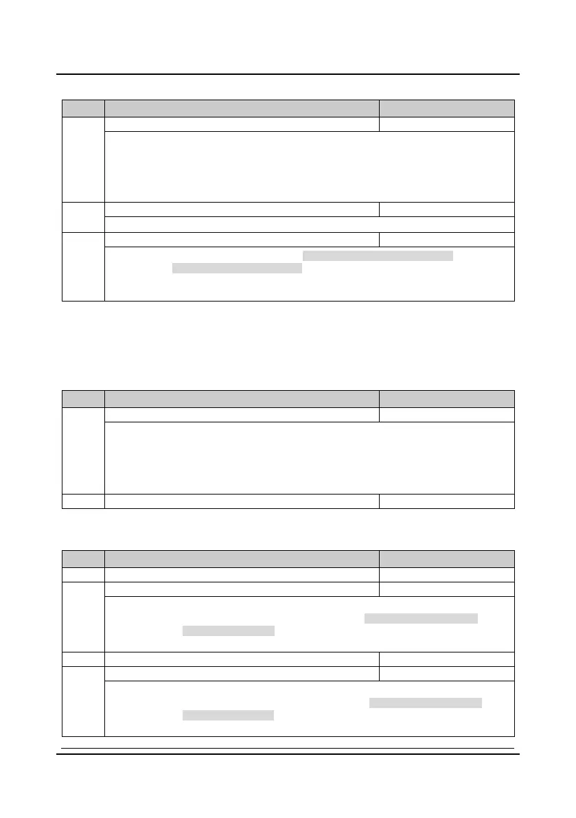
Inverter output load-loss detection fault (F20.03
F20.05)
No. Name Description Range
factory setting
F20.03 Inverter output load-loss detection 0
4
0
0: Disabled. It does not detect inverter output load-loss.
1: It is detecting all the time in running process, and then continues operation after detecting (alarm).
2: It detectes only at the same speed, and then continues operation after detecting (alarm).
3: It is detecting all the time in running process, and then cut off the output after detecting (fault).
4: It is detectes only at the same speed, and then cut off the output after detecting (fault).
F20.04 Inverter output load-loss detection threshold 0
100%
30%
F20.04 defines the current threshold of load-loss. It is a percentage of the inverter’s rated current.
F20.05 Inverter output load-loss detection time 0.00
20.00s
1.00
If the inverter’s output current is smaller than the load-loss detection threshold (F20.04) beyond the
time defined by load-loss detection time (F20.05), the inverter will alarm inverter load-loss fault
(E0018).
• When F20.04 or F20.05 is set to 0, the inverter will not detect load loss fault.
Motor overheating fault (F20.06
F20.07)
It can connect the electronic thermistor embedded motor stator coils to the inverter’s analogue
input in order to protect motor overheating. The connection is shown as the figure
F16.04.
No. Name Description Range
factory setting
Motor overheating signal input type
0: Does not detect the motor overheating.
1: Positive charateristic (PTC).
2: Negative charateristic (NTC).
Note: Only when using HD30-EIO will F20.06 be enabled. It need correctly set the jumpers of
CN3 and CN4 to detect the motor overheating.
Thermistor value at motor overheating
Input and output phase loss fault (F20.08
F20.11)
No. Name Description Range
factory setting
F20.08 Input phase loss detection reference 0
50%
30%
Input phase loss detection time
F20.08 value is a percentage of the inverter’s rated voltage.
When the inverter detects certain input voltage not hit the preset detection reference (F20.08) and
exceed the preset detection time (F20.09), the inverter will perform input phase loss alarm (E0015).
• When F20.08 or F20.09 is set to 0, the inverter will not detect input phase loss fault.
Output phase loss detection reference
F20.11 Output phase loss detection time 0.00
20.00s
3.00
F20.10 value is a percentage of the inverter’s rated current.
When the inverter detects certain output current not hit the preset detection reference (F20.10) and
exceed the preset detection time (F20.11), the inverter will perform output phase loss alarm (E0016).
• When F20.10 or F20.11 is set to 0, the inverter will not detect output phase loss fault.
 Loading...


