Shenzhen Hpmont Technology Co., Ltd Chapter 6 Function Introduction
HD30 Series Inverters User Manual ―75―
No. Name Description Range
factory setting
F09.02 V/f voltage value V3 of motor 1 F09.04
F08.01
0V
V/f frequency value F2 of motor 1
F09.04 V/f voltage value V2 of motor 1 F09.06
F09.02
0V
V/f frequency value F1 of motor 1
F09.06 V/f voltage value V1 of motor 1 0
F09.04
0V
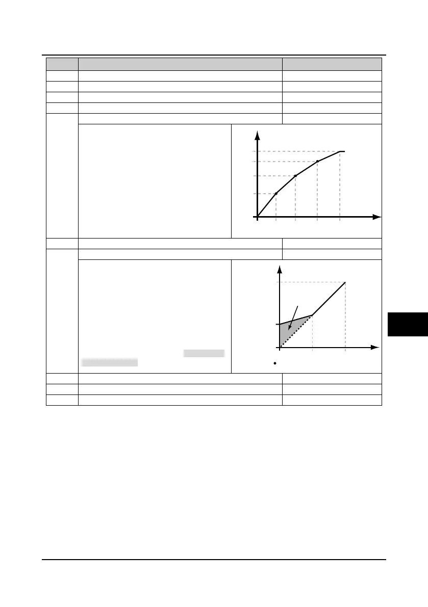
F09.01-F09.06 is the user-definable V/f curve.
• If F09.00 = 4 (user-definable curve), F09.06 is
enabled.
• The V/f curve can be defined by connecting 3
points of (V1, F1), (V2, F2) and (V3, F3), to
adapt to special load.
• According to the actual operation, set proper
curve to meet the requirements of load
characteristics.
F09.08 Cut-off point used for manual torque boost of motor 1 0.0
50.0%
F08.03
10.0%
In order to compensate the torque drop at low
frequency, the inverter can boost the voltage so
as to boost the torque.
• No matter what kind of V/f curve is set by
F09.00, the torque boost is enabled.
If F09.07 = 0, auto torque boost is enabled.
• If F09.07 is set as non-zero, manual torque
boost is enabled.
F09.08 is relative to percentage of motor’s rated
frequency (F08.03).
F09.09 Slip compensation gain of motor 1 0.0
300.0%
100.0
Slip compensation filter time of motor 1
F09.11 Slip compensation limitation of motor 1 0.0
250.0%
200.0
F09.05 F09.03 F09.01 F08.03
F09.06
F09.04
F09.02
F08.01
Frequency
Voltage
0
V1,F1
V2,F2
V3,F3
F09.08max F08.03
Voltage of manual
torque boost
F08.01
Frequency
Voltage
0
Boosted value
F09.08max = 50% F08.03
6

 Loading...


