Chapter 6 Function Introduction Shenzhen Hpmont Technology Co., Ltd.
―60― HD3L Series Controller User Manual
Ref. Code Function Description Setting Range [Default]
F12.18 RLY2 (I/O board) function 0 - 19 [0]
F12.19 RLY3 (I/O board) function 0 - 19 [0]
F12.20 RLY4 (I/O board) function 0 - 19 [0]
0: Unused.
1: Controller is ready.
• Signal ON will output if HD3L has no fault.
2: Controller is running.
• HD3L is in run status and outputs indicating signal.
3: Zero-speed running.
• ON signal will output if output speed of HD3L is zero but HD3L is in run status.
4: Zero-speed.
• ON signal will output if output speed of HD3L is zero.
5: Contactor output control.
• To open / close the output contactor.
6: Brake output control.
• To open / close the brake.
7,8: FDT1, FDT2.
• Refer to F05.12 - F05.13.
9: Speed within FAR signal.
• The indication signal will output when output speed of HD3L is within the FAR range. The detect range
is set by F05.16 (speed within FAR range).
• The indication signal will also output at stop.
10: Up signal output.
• ON signal will output when the elevator is at up running.
11: Down signal output.
• ON signal will output when the elevator is at down running.
12: Under-voltage.
• ON signal will output when HD3L is in under-voltage status.
13: Unused.
14: Controller fault.
• ON signal will output when HD3L has fault.
15: Elevator stop signal.
• When the elevator stops, HD3L will stop and outputs a 2s pulse signal, according to which HD3L
revokes run command.
16 - 19: Unused.
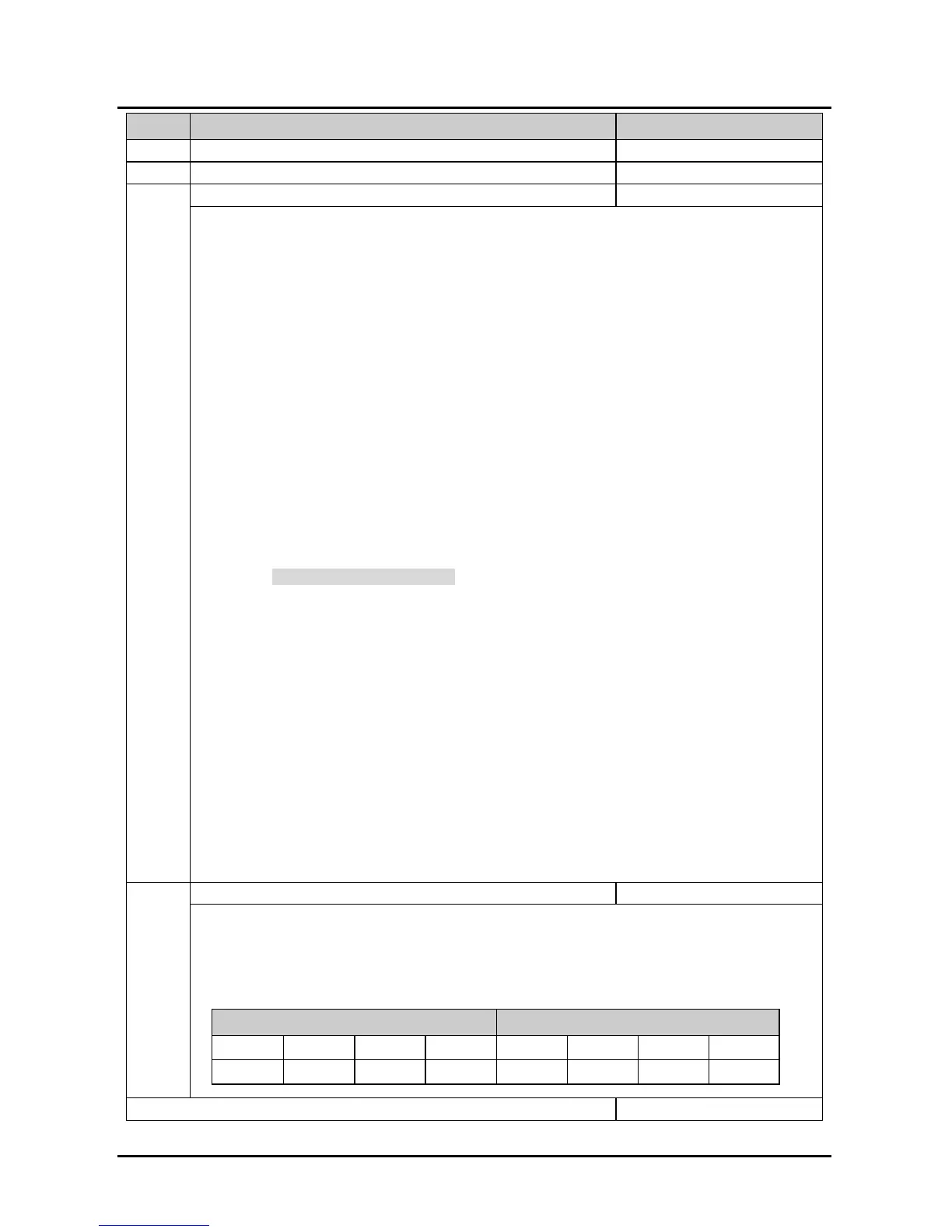
F12.21 Output terminal logic setting 00 - 0x3F [0]
Defines that each bit (binary) represents different output terminal.
• 0: Positive logic. When output terminals are connected to corresponding common port, this logic is
enabled. Otherwise the logic is disabled.
• 1: Negative logic. When output terminals are connected to corresponding common port, this logic is
disabled. Otherwise the logic is enabled.
Tens Units
Bit7 Bit6 Bit5 Bit4 Bit3 Bit2 Bit1 Bit0
- - RLY4 RLY3 RLY2 RLY1 DO2 DO1
123
F12.22 - F2.24 Unused
 Loading...
