8 Replacing components
HSD S.p.A. © - 0108h02a.fm100713
109
8.4.9 Regulating S1 using the kit
After having replaced the sensor as described in paragraph 8.4, calibrate it as follows:
1. for models E40 - F50 use the 11.56 mm gauge and the 0.04 mm thickness spacer
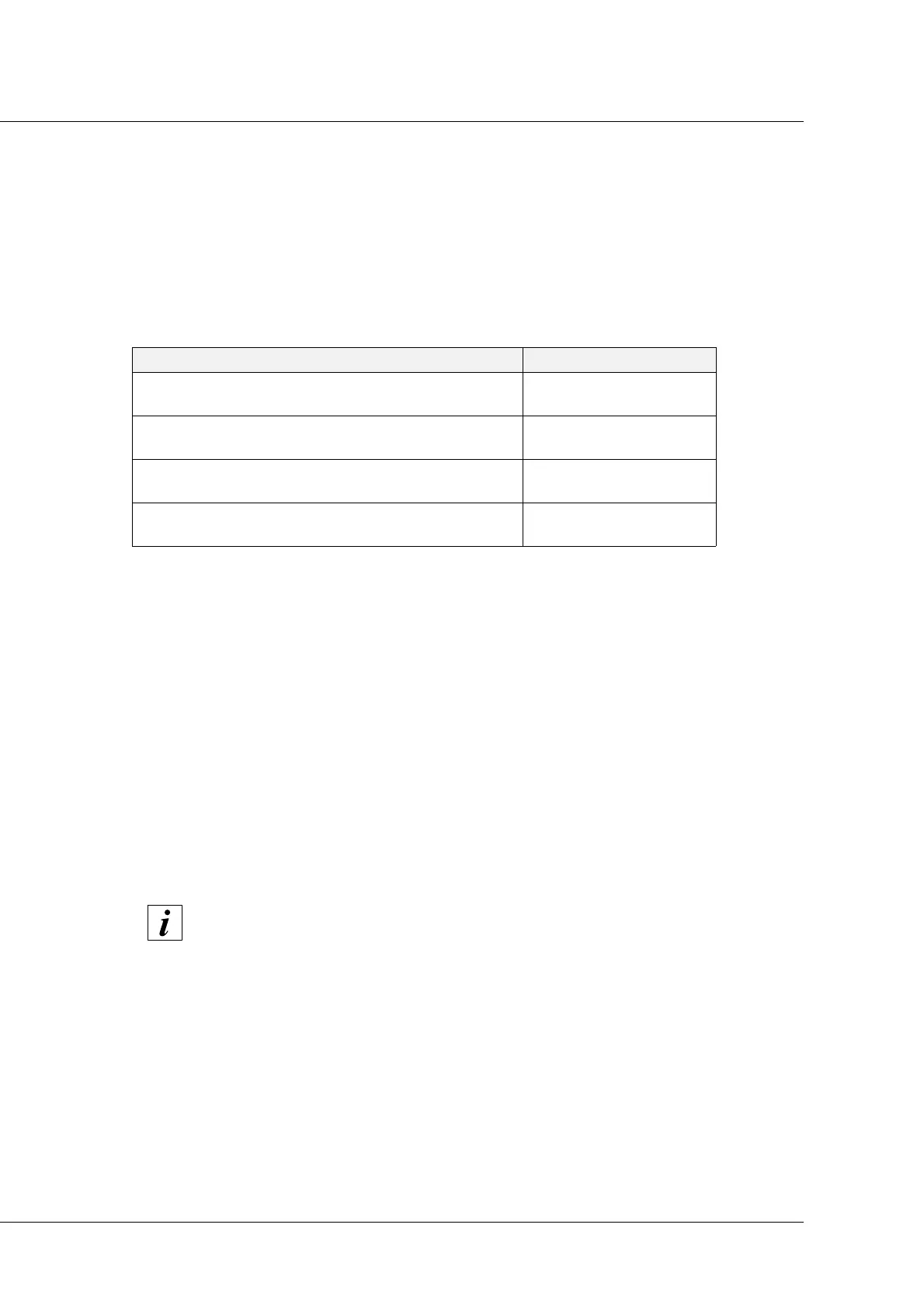
2. Use the gauges and spacers as shown in figures 25 and 26 and check that the signal from
sensor S1 corresponds to that indicated in the following table:
3. Rotate the shaft manually and check that the table is verified for the entire 360° rotation.
4. if not, rotate the sensor until the position necessary to obtain the output described in the table
is found;
5. Fully tighten screw “2”;
6. perform a cycle of 10 tool changes;
7. at the end of the cycle, check that the table shown in point (2) has been satisfied for the entire
360° rotation of the shaft. Otherwise repeat the procedure from the start;
8. if the table is verified, make the machine perform a cycle of 100 tool changes, using the largest
possible number of different tool holders;
9. at the end of the cycle, check that the table shown in point (2) has been satisfied for the entire
360° rotation of the shaft. Otherwise repeat the procedure from the start;
10. If the table in point (2) is satisfied, the calibration of S1 is complete.
CONDITION OUTPUT S1
Gauge locked
thickness spacer interposed
ON
Gauge locked
no thickness spacer interposed
OFF
No collet
(no tool holder)
OFF
Collet open
(tool holder ejected)
OFF
The sensors of the electrospindle ES327 are regulated by axially moving the sensor
instead of rotating it.