6 Operation and regulation
HSD S.p.A. © - 0106h03a.fm100713
81
6.8.9 Description of the inductive sensors
Sensor S1: “tool holder coupled” signal
The signal from sensor S1 indicates the presence of the tool holder cone in the closed collet.
Sensors S1+S4: “HSK Cone locked in the correct position” signal
Sensors S1 and S4 must be connected in series.
Sensor S1 checks the presence of the HSK tool holder cone in the closed collet, and if positive
enables the reading of sensor S4.
When enabled by S1, S4 checks that the mating surfaces of the tool holder cone and the HSK
coupling system are in correct contact.
The output only changes to “ON” if both conditions are verified as positive.
Sensor S2: “collet open” signal
Signal S2 is used during the tool change cycle: it detects the opening of the collet and whether it is
possible to continue with the next phases of the tool-change cycle.
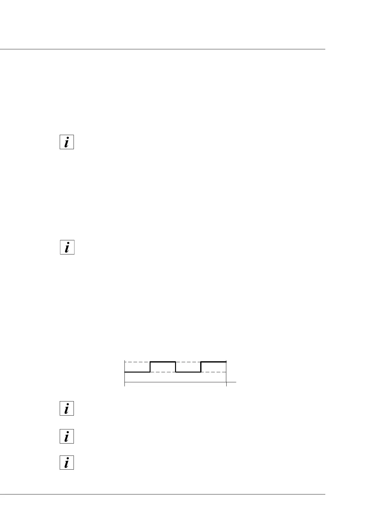
Sensor S3: “shaft stopped” signal
Sensor S3 supplies two “ON” pulses and two “OFF” pulses at each rotation of the shaft, as shown
in the figure below.
Ignore output S1 during the period from the tool release command to the tool couple
command.
Ignore the S1+S4 output during the period from the release command to the couple
tool command.
Over and beyond a given rotation speed, output S3 could appear permanently "ON"
and then subsequently regulate the speed to below the set threshold limit. This is not
a malfunction but depends on the performance of the CNC.
Ignore signal S3 during the tool-change phase as this could randomly appear on one
of the two states (“ON” or “OFF”).
The S3 signal is not present in any version.