5 Installation and commissioning
40
HSD S.p.A. © - h0104k02a.fm091115
Fieldbus connector diagram and logical power
ref. 5 and 6 on page 38
Refer to the user manual "Technical characteristics and E-NETx connection” (for the E-NETx
communication protocol) issued by HSD S.p.A. to correctly use the cable.
If the M12 connector - 5-pin female is not used, plug it with the M12 plug provided. Failure to do so
might compromise the product's IP seal.
Plug the unused connector with the plug provided.
The motor is put in a safety status in case it is switched on and off and if communication is
lacking with the PLC. Safety status means that the shaft is not moving. A special software
command must be used to restore the normal operation .
Digital input connector diagram
ref. from 1 to 4 on page 38
When one or more connectors is not used (from one to four), plug with M8 plugs. Failure to do so
might compromise the product's IP seal.
Plug the unused connectors using M8 plugs.
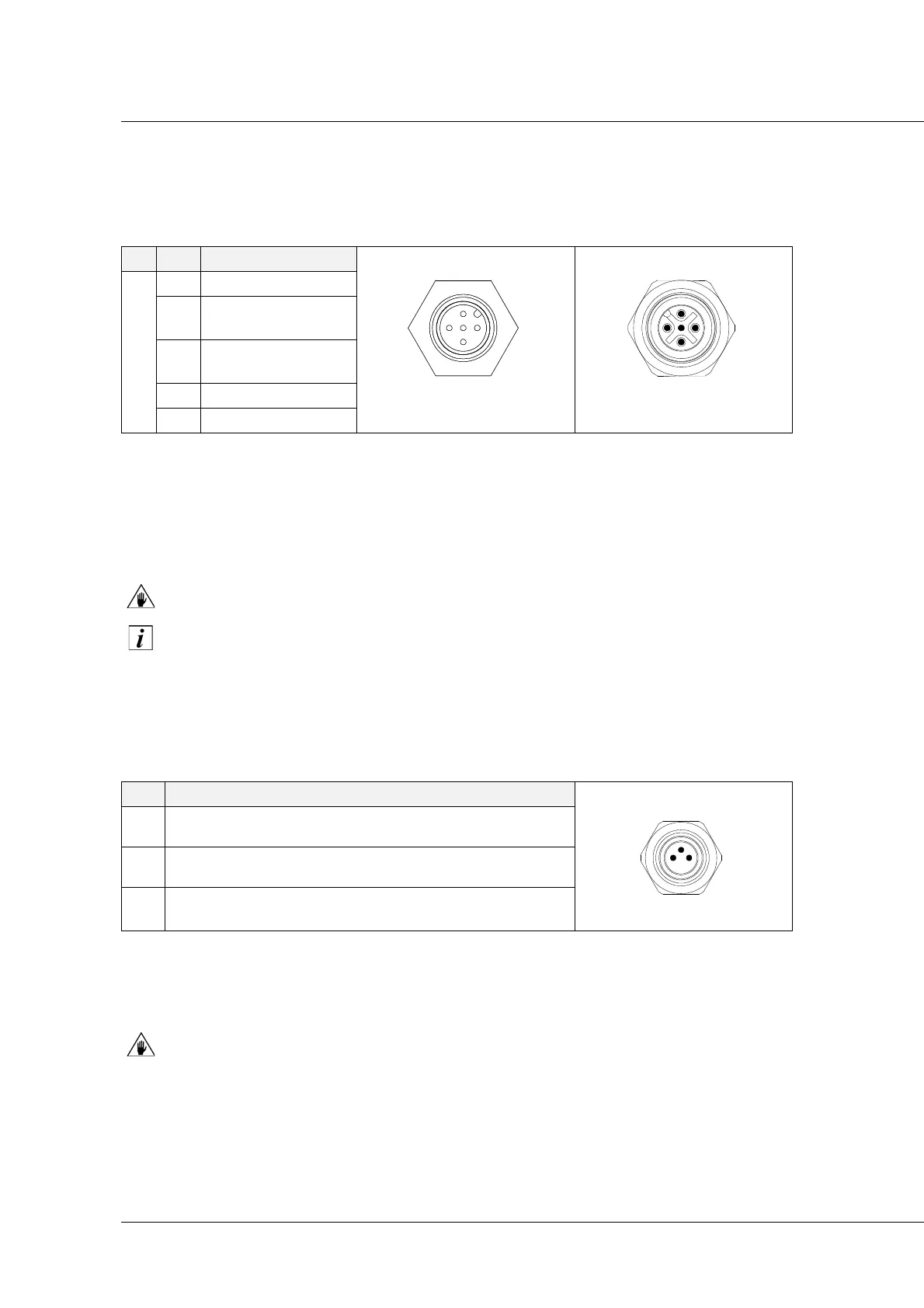
PIN Signal user side view user side view
E-NETx
1 screen
male/IN female/OUT
2
logic power supply
+24 V
DC
*
*
4A MAX allowed, pay attention to the connections in cascade (series).
3
logic power supply
0 V
DC
4 field bus +
5 field bus -
PIN Signal user side view
1 sensor power supply +24 V
DC
*
*
MAX 700 mA output as the equivalent sum of the 4 outputs.
female
3GND
4
external signal input