5 Installation and commissioning
HSD S.p.A. © - h0104k02a.fm091115
41
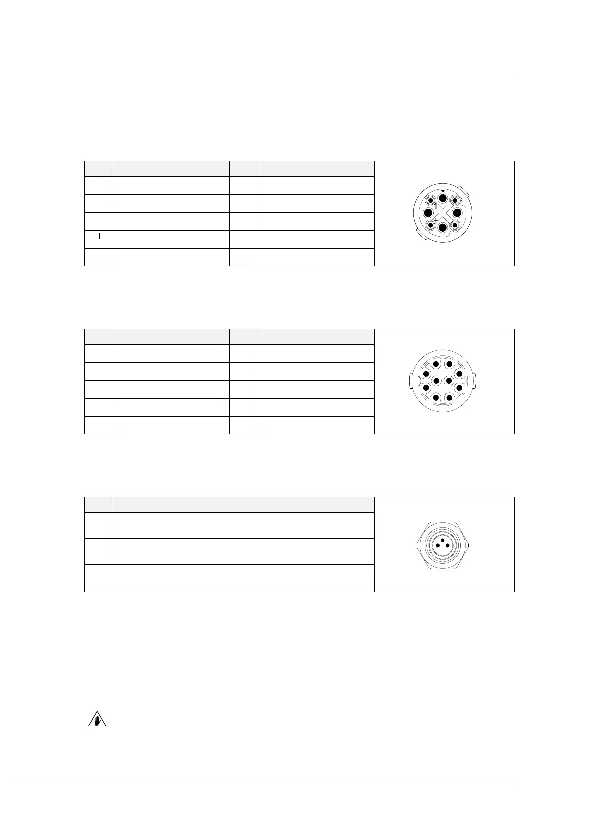
Motor power connector diagram (on CPH 400 only)
ref. 9 on page 38
Encoder connector diagram ( for CPH 400 only)
ref. 10 on page 38
Brake connector diagram (only on CPH 400 version with brake)
ref. 11 on page 38
Operational Earthing (functional earth connection)
An additional earthing is available to have an earting without electromagnetic interference (ref. 8,
page 38). If a correct earthing cannot be performed by means of the support flange or supports/
spacers (due to the presence of painted surfaces or burnished screws), this connection must be
made using an earth cable with eye terminal.
In order to be efficient, this connection must be as short as possible (MAX 30 CM).
PIN Signal PIN Signal user side view
A U Phase 2 Not used
female
B V Phase + Not used
C W Phase - Not used
Earth
1 Not used
PIN Signal PIN Signal user side view
1A+ 6Z-
female
2A- 7+5V
3 B+ 8 +24V
4B- 90V
5Z+ 10NC
PIN Signal user side view
1 brake power supply +24 V
DC
*
*
Output MAX 400 mA
female
3GND
4
screen