25
LP-542 REV. 7.16.15
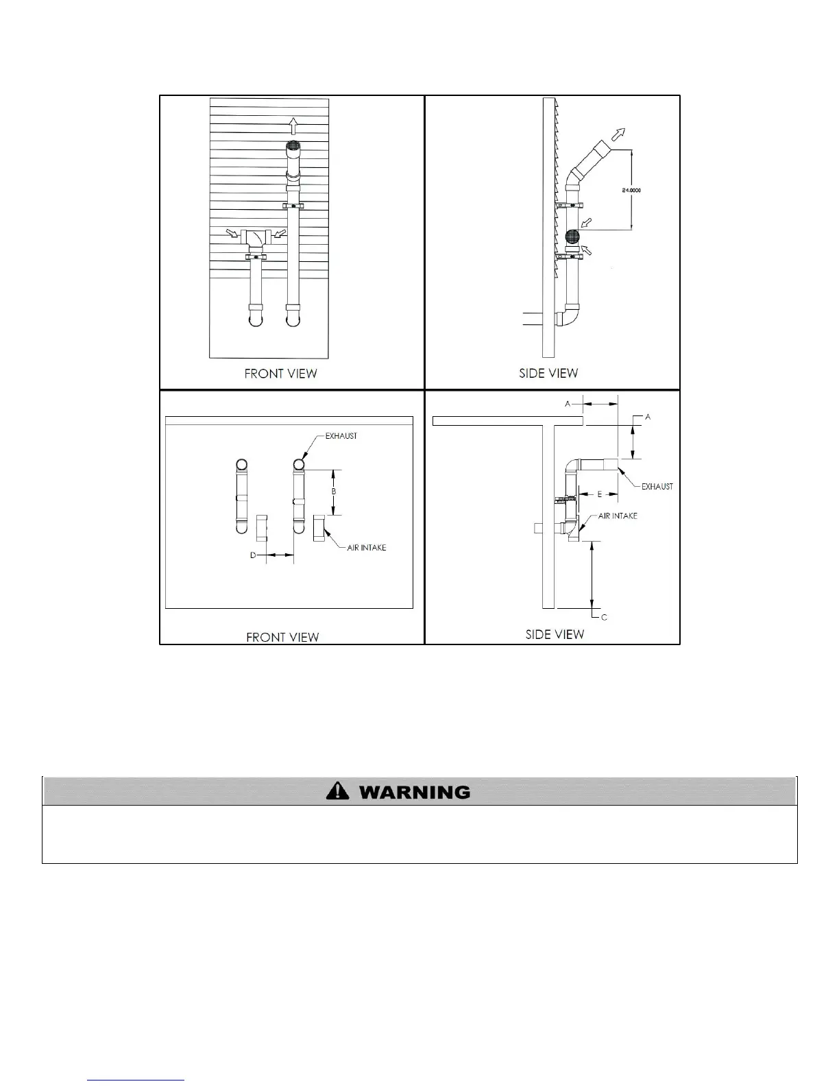
3. Snorkel Venting
Figure 11 – Horizontal Venting - NOTE: Drawing is meant to demonstrate system venting ONLY.
NOTES:
A. For every 1” of overhang, the exhaust vent must be located 1” vertical below overhang (overhang means top of building structure and not two
adjacent walls [corner of building]).
B. Typical installations require 12” minimum separation between bottom of exhaust outlet and top of air intake.
C. Maintain 12” minimum clearance above highest anticipated snow level or grade (whichever is greater).
D. Minimum 12” between vents when installing multiple vents.
E. 12” minimum beyond air intake.
All vent pipes must be glued, properly supported, and the exhaust must be pitched a minimum of ¼” per foot back to the boiler to allow
drainage of condensate. When placing support brackets on vent piping, the first bracket must be within 1 foot of the boiler and the
balance at 4 foot intervals on the vent pipe. Boiler venting must be readily accessible for visual inspection for the first three feet from the
boiler.

 Loading...