46
LP-542 REV. 7.16.15
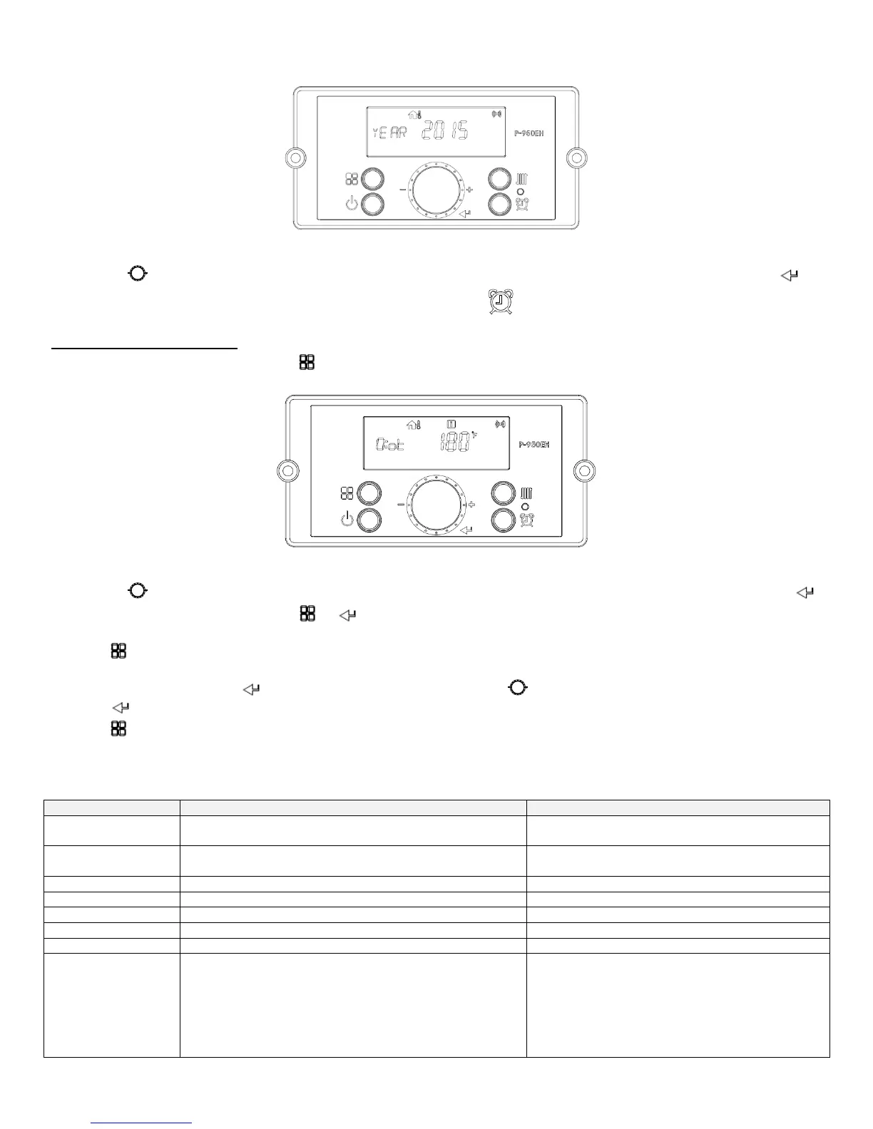
Figure 39 – Storage Mode Screen
Turn the dial counterclockwise to lower and clockwise to raise the current time setting. After changing the setting, press the
button to save the setting. The next adjustable setting will appear. Press the button to return to the main screen.
F. STATUS DISPLAY MODE
Status Display Mode will activate when the button is pressed and held for five seconds when the display panel is powered ON.
Figure 40 – Status Mode Screens
Turn the dial counterclockwise and clockwise to scroll through the displayed parameters. To view parameter details, press the
button at the appropriate screen. Press the or buttons to leave the parameter.
Press the button again to return to Operation Mode.
To turn on Lock Mode, press the button at the d:Lc parameter. Turn the dial counterclockwise or clockwise to scroll On or Off.
Press the button to save the selection and return to the parameters.
Press the button again to return to Operation Mode.
NOTE: The Control System will not allow the changes if Lock Mode is activated. Lock Mode will have to be turned off before making
further changes.
Outdoor Temperature
(If --- is displayed, no outdoor sensor is connected)
Current Outdoor Sensor Temperature
0-10V Display
(If --- is displayed, no 0-10V input is connected)
Current Voltage of 0-10V Input
Current CH Target Temperature
Current CH Return Temperature
CH Supply Temperature (Operating Temperature)
Current CH Supply Temperature
Current Exhaust Gas Temperature
Indirect DHW Tank Temperature
(If OFF is Displayed DHW Sensor is Not Connected)
Current DHW tank temperature measured by the
indirect tank sensor (7250P-325) will be displayed
If OFF is displayed - a mechanical aqua stat is
connected and the contact is open, or no sensor is
connected.
If ON is displayed - a mechanical aqua stat is
connected and the contact is shorted.

 Loading...