55
LP-542 REV. 7.16.15
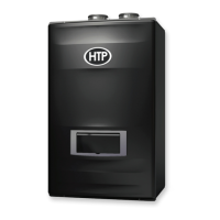
Figure 47 – Outdoor Reset Curve – See Installer Mode for Curve Setting Descriptions
K. 0-10 VOLT INPUT
1. A signal from a building management system may be connected to the boiler to enable remote control. This signal should be a 0-10
volt positive-going DC signal. When this input is enabled, a building control system can be used to control the set point temperature of
the boiler. The control interprets the 0-10 volt signal as follows; when the signal is between 0 and 1.5 volts, the boiler will be in standby
mode, not firing. When the signal rises above 1.5 volts, the boiler will ignite. As the signal continues to rise towards its maximum of 10
volts, the boiler will increase in set point temperature.
2. Connect a building management system or other auxiliary control signal to the terminals marked for this purpose on the boiler
terminal block (shown in Piping Diagrams, this manual). Caution should be used to ensure that the 0-10 VOLT + connection does not
become connected to ground.
NOTE: Ensure that the polarity of the connections from the external modulating boiler controller to the boiler is correct. Reversed
polarity could lead to erratic and/or no response from the boiler controller.
NOTE: Outdoor Temperature Mode Icon on the display will flash if an Outdoor Sensor or 0-10 Volt is not connected to the boiler.
0-10 V INPUT TABLE:
When outside voltage is applied to the connector (2) in the wiring diagram,
1. The Outdoor temperature sensor does not work.
2. Symbol is displayed.
3. The heating temperature is automatically set according with the external voltage input.
NOTE: 0-10V is prioritized over T/T. If input voltage is less than 1.5V then T/T will operate.
The range of input voltage is approximately 1.5[V] ~ 10[V] and the heating temperature settings according to this range are as follows.
Table 26 – 0-10V Input Voltages and Associated Temperatures

 Loading...