60
LP-542 REV. 7.16.15
ADJUSTING GAS PRESSURE AT THE BOILER
1. Open the gas line and water valves.
2. Use a Phillips Head screwdriver to remove the boiler front cover.
Remove the front cover.
3. Loosen the gas inlet pressure tap screw three turns a screwdriver.
Connect the manometer to the inlet gas pressure port. See Figure 48.
4. Turn on power to the boiler and turn up the thermostat to make a call
for heat.
5. The minimum and maximum inlet gas line pressures must meet the
requirements shown in Table 28.
Table 28 – Gas Pressure Requirements
6. Remove the manometer. Close the screw on the gas inlet pressure tap.
J. SETTING AND VERIFYING THE COMBUSTION SETTING
1. After the boiler has fired, flip DIP switch seven (7) to the ON position (low fire). Proceed to check boiler combustion values.
NOTE: Use a combustion analyzer to ensure CO and CO
2
values are within the range shown in Table 28.
It is required to use a combustion analyzer to verify final adjustment according to the combustion chart (Table 29). Failure to do so
could result in serious personal injury or death.
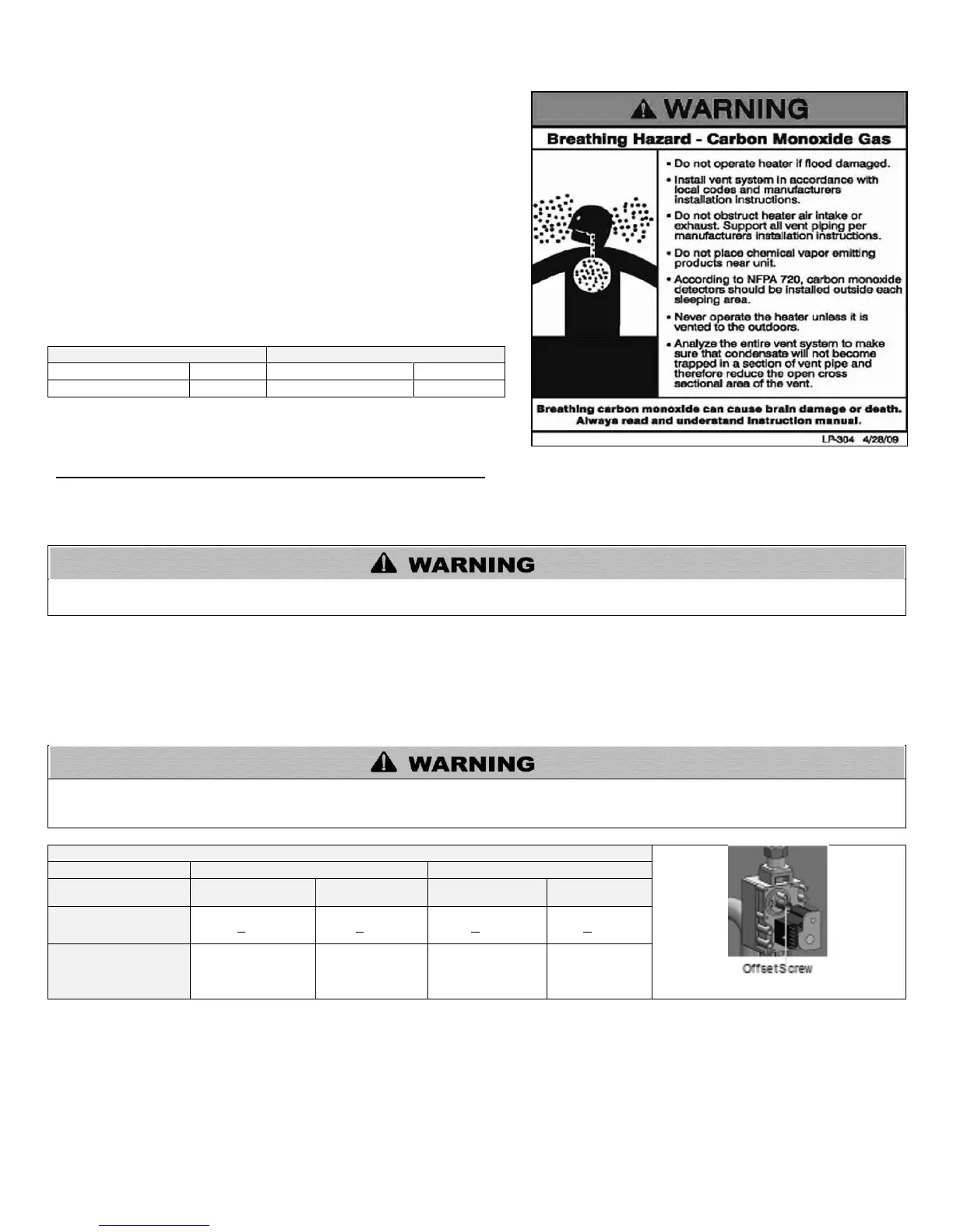
If the readings obtained are lower or higher than the combustion readings in Table 29, use a 4mm Allen key to adjust the offset screw in
a clockwise (positive) or counterclockwise (negative) direction (approximately 1/4 turn). See Figure 49. Check your combustion values.
Repeat this procedure until the values obtained on the combustion analyzer agree with those stated in Table 29.
NOTE: If the boiler makes a whistling sound (harmonics) at low fire, adjust the offset screw in a clockwise (positive) direction
(approximately 1/8 turn). Check your combustion values and ensure they agree with those stated in Table 29 before proceeding.
It is very important that this conversion be set within the recommended CO measurements listed in Table 29. Visually looking at the
burner does not determine combustion quality. Failure to measure combustion with a Combustion Analyzer and set the throttle within
the recommended CO measurements could result in property damage, severe personal injury, or death.
Figure 49 – Gas Valve Offset Screw
Table 29 – Combustion Settings
2. When low fire settings have been obtained, flip DIP switch seven (7) to its original (OFF) position. This will return the boiler to normal
mode.
3. Flip DIP switch six (6) to ON (high fire). Again check combustion readings with a combustion analyzer.
4. When complete, flip DIP switch six (6) to its original (OFF) position. This will return the boiler to normal mode.

 Loading...