66
LP-542 REV. 7.16.15
1. Ensure the boiler is powered off and has had time to cool.
2. Remove the hose clamp attaching the condensate trap to the condensate hose from the heat exchanger. Remove the clear plastic
hose from the hose barb. Remove the condensate hose clamp to detach the condensate trap from the drain tube. Remove the
condensate trap from the boiler.
3. Remove the bottom cap from the condensate trap.
4. Flush trap with fresh water to remove debris from the trap.
NOTE: Ensure the float moves freely within the trap. If the float does not
move, DO NOT reinstall the trap.
5. When the condensate trap is sufficiently clean, reinstall the bottom cap on
the trap.
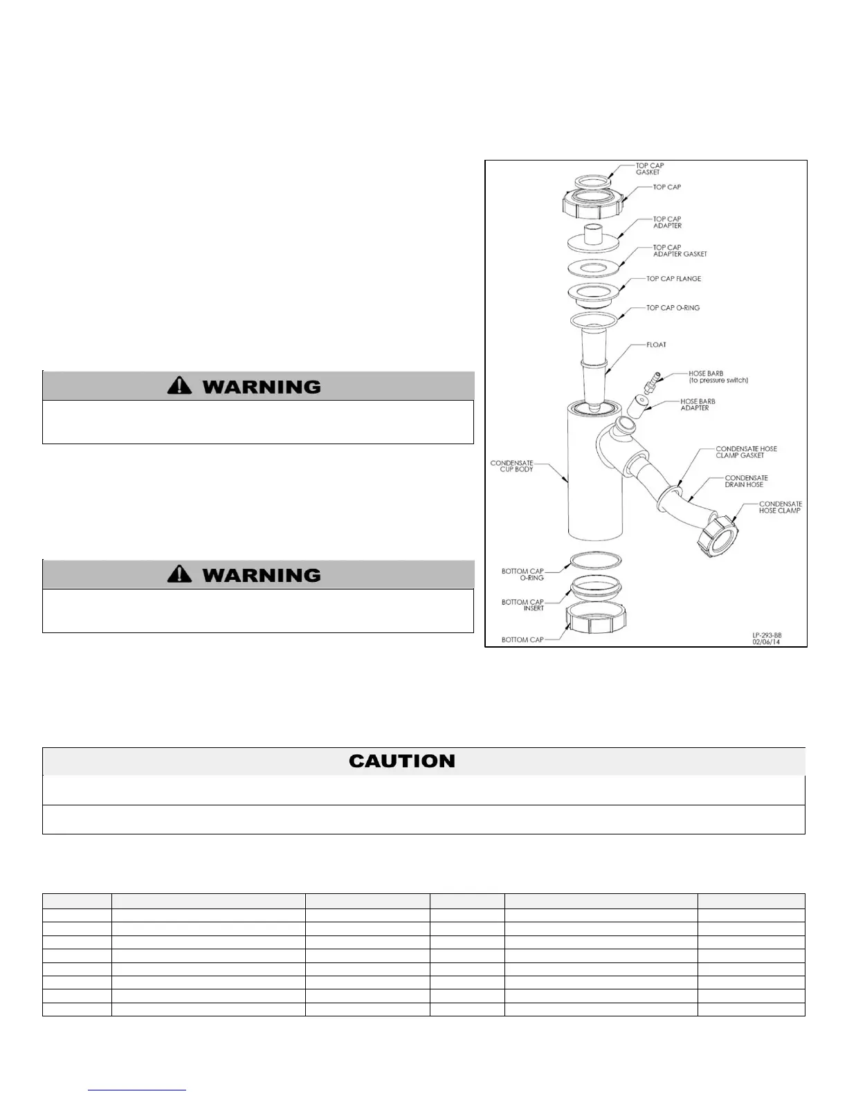
NOTE: Ensure all parts shown in Figure 52, Condensate Detail, are installed
with the condensate trap. If any parts are missing, DO NOT reinstall the
trap. Replace the entire assembly.
6. Fill the condensate trap with fresh water prior to reassembly on the boiler.
7. Install the condensate trap on the condensate hose from the heat
exchanger. Use the hose clamp to secure the trap. Attach the clear plastic
hose onto the hose barb. Reinstall the condensate hose clamp to detach the
condensate trap from the drain tube.
Do not operate the boiler without the clear hose attached from the hose
barb to the pressure switch. Failure to follow this warning could result in
property damage, serious personal injury, or death.
8. If a condensate neutralizer kit is installed with the boiler, check the
assembly when cleaning the condensate trap, and replenish the limestone
chips if necessary. When replacing the limestone chips, take care to ensure chips are no smaller than ½” to avoid blockage in
condensate piping (for piping details, refer to condensate neutralizer installation instruction.)
9. Check condensate piping for sagging and/or leakage. Repair any sags or leaks before restoring power to the boiler.
It is very important that the condensate piping be no smaller than ¾”. To prevent sagging and maintain pitch, condensate piping should
be supported with pipe supports, and pitched ¼” per foot to allow for proper drainage.
The condensate line must remain unobstructed, allowing free flow of condensate. If condensate freezes in the line, or if line is
obstructed in any other manner, condensate can exit from the tee, resulting in potential water damage to property.
10. If the boiler has a condensate pump, ensure the pump operates properly before considering maintenance complete.
REPLACEMENT PARTS
M4 X 14 PH + Self Tapping
M4 X 20 TH + Self Tapping
M4 X 10 TH + Self Tapping
Table 33 – Replacement Bolts and Nuts
Do not install the condensate assembly if a component is lost or missing.
Replace the entire assembly. Failure to follow this warning could result in
property damage, serious personal injury, or death.
Figure 52 – Condensate Detail

 Loading...