39
LP-542 REV. 7.16.15
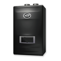
Figure 29 – Manual Power Switch and Boiler Plug Details
If the boiler display does not come ON, first check the plug. Then check the electrical panel circuit breaker and reset it if necessary. If
the circuit breaker trips again, do not reset. Disconnect the plug and have a qualified technician diagnose the problem.
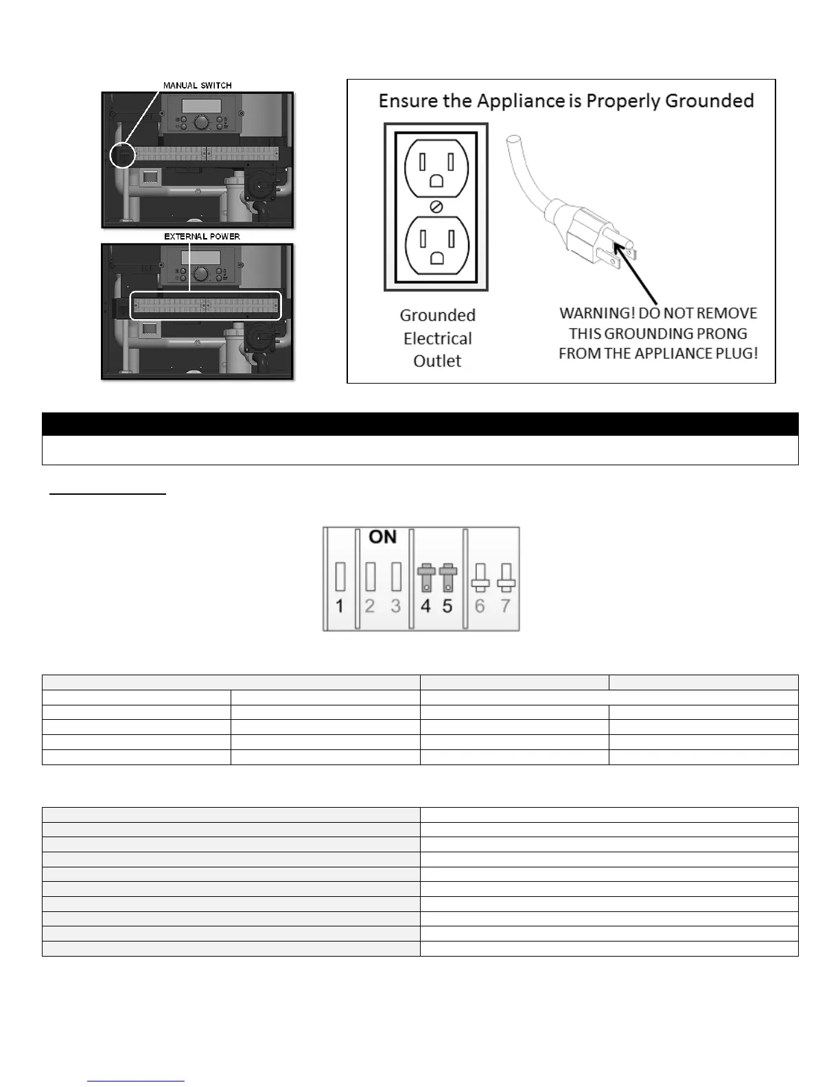
C. DIP SWITCHES
There is one set of DIP switches. The boiler is default set at the factory to operate on Natural Gas with a 3” vent.
Figure 30 – Factory Default Dip Switch Detail
DIP SWITCH GROUP
Table 17 – DIP Switches 4 - 7
SYSTEM CONTROL SETTINGS
MAXIMUM FLAME DETECTING VOLTAGE
Maximum 10 seconds, minimum 1 second
SAFETY TIME (IGNITING TIME) (Ts)
2 minutes (1
st
: 1 minute, 2
nd
: 1 minute)
OVER-HEATING 1,2,3 PROTECTION DETECTION TIME
PUMP 1 POST CIRCULATING TIME (T1pv)
PUMP 2 POST CIRCULATING TIME (T2pv)
HIGH AND LOW WATER LEVEL DETECTION TIME
HIGH AND LOW WATER LEVEL RECOVERY TIME
Table 18 – System Control Settings

 Loading...