59
LP-542 REV. 7.16.15
F. CHECK THERMOSTAT CIRCUIT(S)
1. Disconnect the two external wires connected to the boiler thermostat terminals (low voltage terminal strip).
2. Connect a voltmeter across these two incoming wires with power supplied to the thermostat circuits. Close each thermostat, zone
valve and relay in the external circuit one at a time and check the voltmeter reading across the incoming wires.
3. There should NEVER be a voltage reading.
4. If a voltage reading does occur under any condition, check and correct the external wiring. (This is a common problem when using 3-
wire zone valves.)
5. Once the external thermostat circuit wiring is checked and corrected if necessary, reconnect the external thermostat circuit wires to
the boiler low voltage terminal strip. Allow the boiler to cycle.
G. CONDENSATE REMOVAL
1. This is a high efficiency condensing boiler. Therefore, the boiler has a condensate drain. Condensate fluid is nothing more than water
derived from combustion products, similar to that produced by an automobile when it is initially started.
Condensate is slightly acidic (typically with a pH of 3 to 5) and must be piped with the correct materials. Never pipe the condensate
using steel, copper, brass or other materials that will be subject to
corrosion. Plastic PVC or CPVC pipe are the only approved materials.
A condensate neutralizer, if required by local authorities, may be
purchased from HTP (7450P-212).
2. It is very important that the minimum ¾” condensate line is sloped
downward away from the boiler to a suitable inside drain. If the
condensate outlet on the boiler is lower than the drain, you must use a
condensate removal pump, available from HTP (554200). This pump
is equipped with two leads that can be connected to an alarm or
another type of warning device to alert the user of a condensate
overflow, which, if not corrected, could cause property damage.
3. If a long horizontal run is used, it may be necessary to create a vent
in the horizontal run to prevent a vacuum lock in the condensate line.
4. Do not expose the condensate to freezing temperatures.
5. It is very important you support the condensate line to assure
proper drainage.
H. FINAL CHECKS BEFORE STARTING BOILER
1. Verify the boiler and system are full of water and all system
components are correctly set for operation.
2. Fill the condensate trap with water.
3. Verify electrical connections are correct and securely attached.
4. Inspect exhaust vent and intake piping for signs of deterioration from corrosion, physical damage, or sagging. Verify exhaust vent
and intake piping are intact and correctly installed per Venting Section (this manual) and local codes.
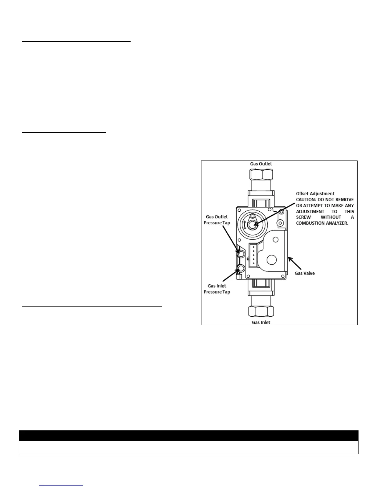
I. ADJUSTING GAS PRESSURE AT THE BOILER
NOTE: Refer to Figure 48 when adjusting gas pressure. Loosen the screw before checking the gas inlet pressure.
1. The boiler and its individual shutoff valve must be disconnected from the gas supply piping system during any pressure testing of the
system at test pressures greater than ½ psi (3.5 kPa).
2. The boiler must be isolated from the gas supply piping system by closing its individual manual shutoff valve during any pressure
testing of the gas supply piping system at test pressures equal to or less than ½ psi (3.5 kPa).
Do not fire (operate) the boiler until all connections have been completed and the heat exchanger is filled with water. Doing so will
damage the boiler and void the warranty.
Figure 48 –Gas Valve Detail

 Loading...