47
LP-542 REV. 7.16.15
Current CH Overheat Temperature
Cycle : 10 times displayed
Cycle : 10,000 times displayed
Capacity of the Master (percentage)
Percentage of Master Unit Running
Total Cascade Capacity (percentage). This icon will only
be displayed when the units are in cascade mode.
NOTE: This index will only be shown in cascade mode.
Percentage of cascade units running.
This screen shows the overall cascade power
output. The range of this value of boilers
communicating with the Master x 100. For
example, if 8 boilers are connected and
communicating, the maximum cascade power is
800%. Range: 0-100%
Capacity of individual boilers (percentage). This icon will
only be displayed when the units are in cascade mode.
Percentage of each cascade units running.
Ex. M, F1, F2, ….
System Temperature (Cascade Mode)
(If Sensor is Not Connected, Screen will Display 0F or 0C)
NOTE: This index will only be shown in cascade mode.
Current System Temperature (Cascade Mode)
Table 22 – Status Mode Display Screen Descriptions
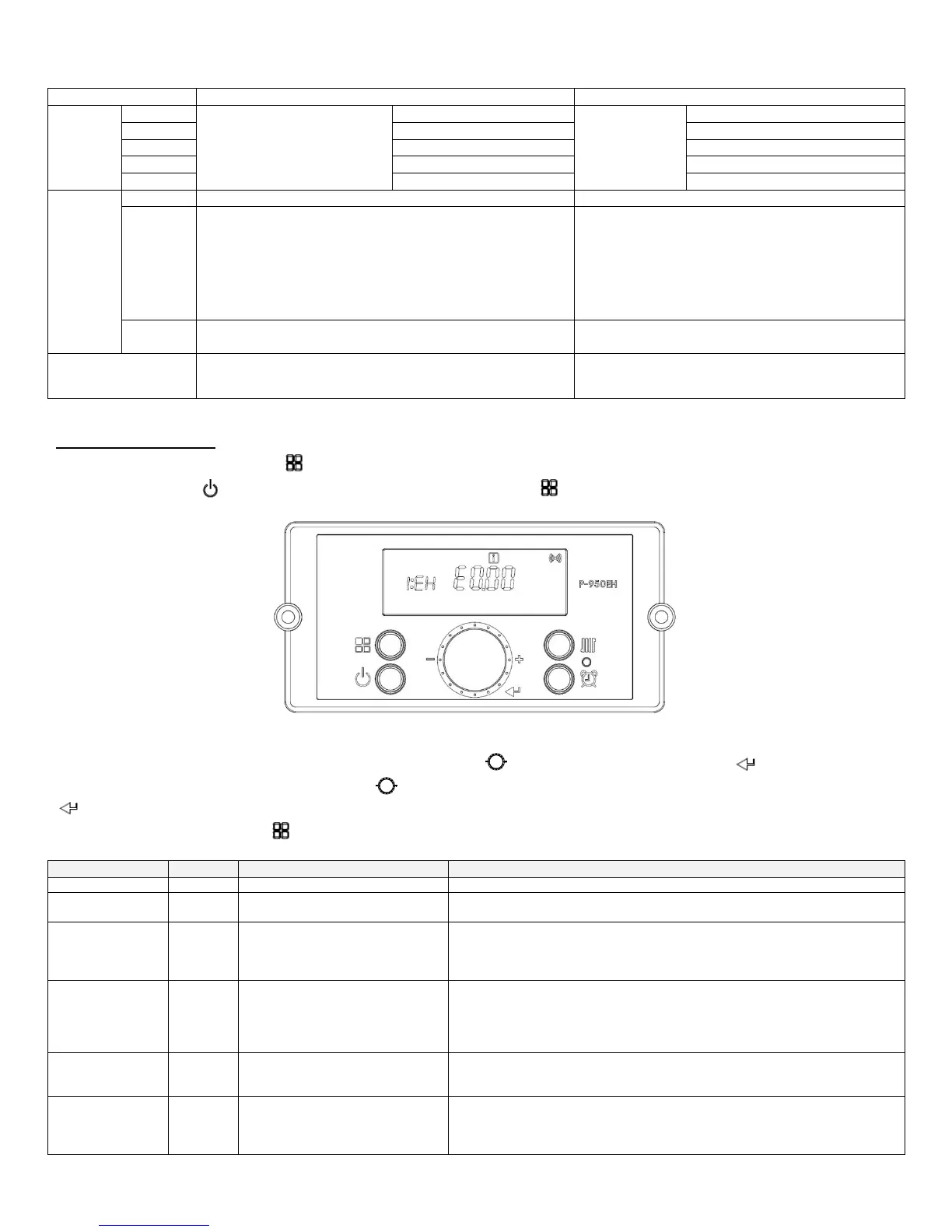
G. INSTALLER MODE
Installer Mode will activate when the button is pressed and held for five seconds while the display is powered OFF. If the display is
powered on, press the button to turn it off before pressing and holding the button for five seconds.
Figure 41 – Installer Mode Screens
Toggle through items that can be viewed/changed by turning the dial . To view/change an item, press the button. Some
displayed items can be changed by turning the dial counterclockwise to lower and clockwise to raise the displayed value. Press the
button again to save settings.
To leave Installer Mode, press the button again. The display will return to power off mode.
Check last 10 error codes (E0 - E9)
Select “ON” to delete error code history
Range: ON or OFF
System Reset
(Factory Settings)
Select “ON” to reset to factory setting
(Burner operation time, Ignition cycles, and Supply power time will not be reset.
See Functions 14 and 15.)
Range: ON or OFF
Maximum Outdoor Temperature
When used with an outdoor sensor, sets the maximum outdoor design
temperature for the system design. Warm weather shut down will disable the
boiler if the programmed outdoor temperature is exceeded. Maximum outdoor
temperature must be set 9
o
F above the minimum outdoor temperature.
Range: (Minimum Outdoor Temperature + 9
o
F) to 110
o
F
Minimum Outdoor Temperature
Sets the minimum outdoor design temperature for the system. Minimum
outdoor temperature must be set 9
o
F below the maximum outdoor temperature.
Range: -4
o
F to (Maximum Outdoor Temperature - 9
o
F)
Maximum Supply Temperature
Sets the maximum design supply temperature based on the minimum outdoor
design temperature. Maximum supply temperature must be set at least 9
o
F
above the minimum supply temperature.
Range: (Minimum Supply Temperature + 9
o
F) - 180
o
F

 Loading...