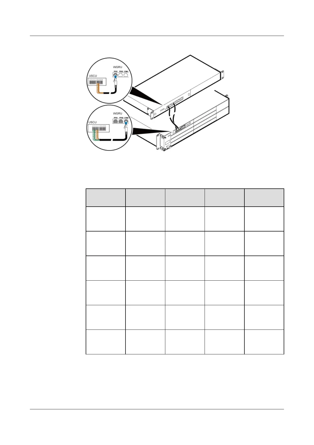
Figure 12-10 Installing a PPS signal cable and GPS signal cable
Table 12-1 Pin assignment for the wires of a PPS signal cable and GPS signal cable
Port Pin
Assignment
Port Silkscreen Color
WGRU-PPS1 Pin 1-
CLK1_PPS_T
XD+
USCU-RGPS 1S+ White and
orange
WGRU-PPS1 Pin 2-
CLK1_PPS_T
XD-
USCU-RGPS 1S- Orange
WGRU-
COM1
Pin 1-
COM1_COM
RXD+
USCU-RGPS TX+ White and
orange
WGRU-
COM1
Pin 2-
COM1_COM
RXD-
USCU-RGPS TX- Orange
WGRU-
COM1
Pin 3-
COM1_COM_
TXD+
USCU-RGPS RX+ White and
green
WGRU-
COM1
Pin 6-
COM1_COM_
TXD-
USCU-RGPS RX- Green
3. Route and bind the cables. For details, see 12.4.1 Cabling Requirements.
Step 6 Label the installed cables. For details, see Attaching an L-Shaped Label.
----End
DBS3900 (Ver.B)
Installation Guide
12 Indoor Scenario with DC Power Supply (BBU Installed in
a 19-Inch Rack)
Issue 06 (2011-09-15) Huawei Proprietary and Confidential
Copyright © Huawei Technologies Co., Ltd.
411