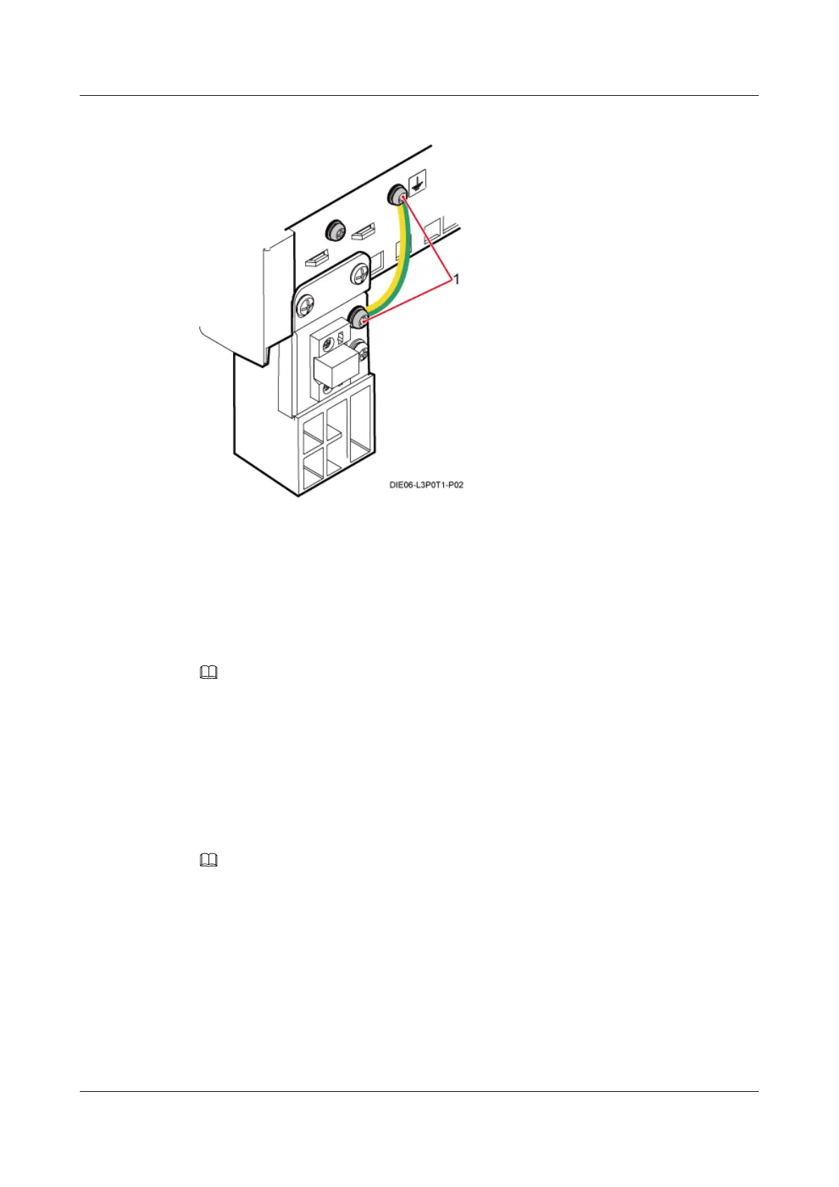
Figure 13-41 Installing the PGND cable
(1) OT terminal (M4)
----End
13.5 Installing IMB03 Cables
This section describes cable connections and the process of installing cables.
NOTE
In the DC power supply scenario, a BBU power cable must be connected to each UPEU if two UPEUs are
installed in the BBU. The 3V3 power connector at one end of each BBU power cable is connected to the
–48V port on each UPEU in the BBU, and the easy power receptacle (pressfit type) connectors at the other
end are connected to the LOAD6 and LOAD7 ports on the DCDU-03B, respectively.
13.5.1 Cabling Requirements
Cables must be routed according to the specified cabling requirements to prevent signal
interference.
NOTE
If a cable listed below is not required, skip the routing requirements of the cable.
General Cabling Requirements
The bending radius of the cables must meet the following specifications:
l The bending radius of the 7/8'' feeder must be more than 250 mm (9.84 in.), and the bending
radius of the 5/4'' feeder must be more than 380 mm (14.96 in.).
l The bending radius of the 1/4'' jumper must be more than 35 mm (1.38 in.). The bending
radius of the super-flexible 1/2'' jumper must be more than 50 mm (1.97 in.), and the bending
radius of the ordinary 1/2'' jumper must be more than 127 mm (5 in.).
DBS3900 (Ver.B)
Installation Guide 13 Indoor Scenario (BBU Installed in an IMB03)
Issue 06 (2011-09-15) Huawei Proprietary and Confidential
Copyright © Huawei Technologies Co., Ltd.
465