2. Connect the RJ-45 connector at the other end of the signal cable to COM OUT of the
CMUA in the cabinet.
Step 4 Route the cables by referring to 8.5.1 Cabling Requirements and use cable ties to bind the
cables.
Step 5 Attach labels to the installed power cable and monitoring signal cable. For details, see Attaching
a Sign Plate Label and Attaching an L-Shaped Label.
----End
8.4.5 Installing the GPS Surge Protector
This section describes the procedure and precautions for installing the GPS surge protector and
related cables.
Context
NOTE
Only a dual-satellite receiver needs to be installed onsite.
Procedure
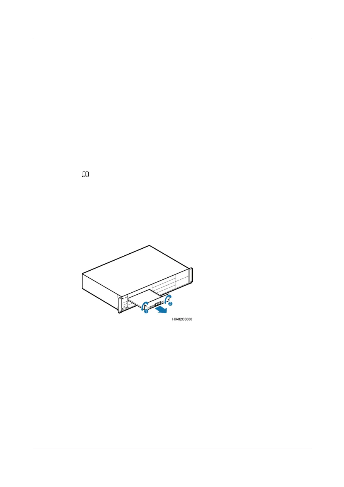
Step 1 Remove the two M3 screws on the panel, and then pull out the USCU, as shown in Figure
8-51.
Figure 8-51 Removing the USCU.
Step 2 Install a satellite receiver on the USCU, as shown in Figure 8-52.
1. Remove the three M1.6 screws from the USCU.
2. Align the mounting holes on the satellite receiver with the bolts on the USCU.
3. Tighten the three M1.6 screws that were removed in Step 2.1 to 0.1 N·m.
4. Connect one end of the RF jumper to the RF port on the satellite receiver and the other end
to the GPS port on the USCU.
DBS3900 (Ver.B)
Installation Guide
8 Outdoor Scenario with DC Power Supply (BBU Installed
in a +24 V DC APM30H)
Issue 06 (2011-09-15) Huawei Proprietary and Confidential
Copyright © Huawei Technologies Co., Ltd.
253