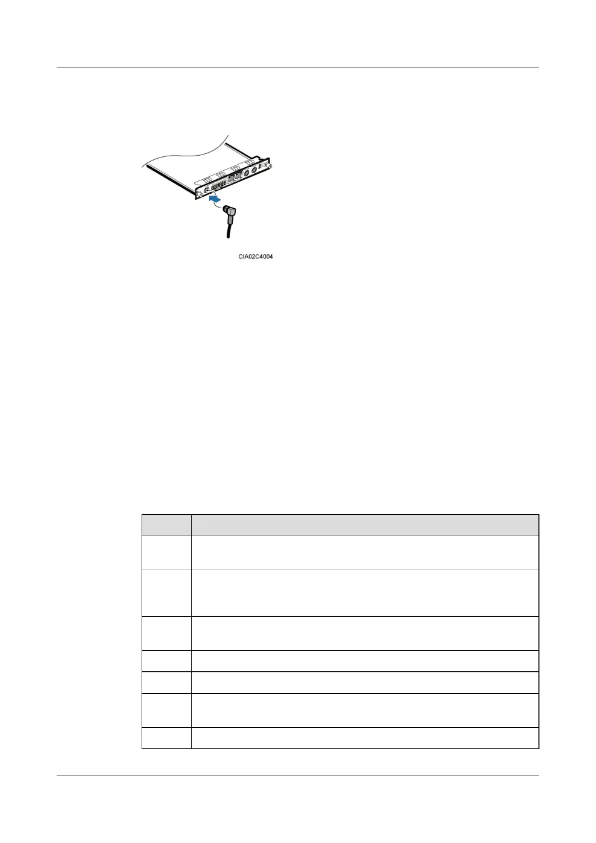
Step 4 Connect the GPS clock signal cable to the GPS port on the USCU, as shown in Figure 11-30.
Figure 11-30 Installing a GPS Clock Signal cable
Step 5 Route the cables by referring to 11.4.1 Cabling Requirements, and then use cable ties to bind
the cables.
Step 6 Label the installed cables by referring to Attaching an L-Shaped Label.
----End
11.5 Installation Checklist
Check the installation items, installation environment, and cable-related items after the cabinets
and devices are all installed.
Cabinet Installation Checklist
Table 11-6 describes the cabinet installation checklist.
Table 11-6 Cabinet installation checklist
No.
Item
1 The installation position of the cabinet strictly complies with the engineering
design.
2 In the wall-mounted scenario, the holes of the mounting ears are well aligned with
the holes of the expansion bolt assemblies. In addition, the mounting ears are
secured on the wall evenly and steadily.
3 In the metal-pole-mounted scenario, the supports for the metal pole are secure on
the floor.
4 If the cabinet is installed on the floor, the base is securely installed.
5 Either the horizontal error or vertical error of the cabinet is less than 3 mm.
6 All the bolts, especially those for electrical connections, are tight. Both the spring
washer and the flat washer are installed in the correct sequence.
7 The cabinet is neat and clean.
DBS3900 (Ver.B)
Installation Guide
11 Indoor Scenario with DC Power Supply (BBU Installed
on a Wall)
Issue 06 (2011-09-15) Huawei Proprietary and Confidential
Copyright © Huawei Technologies Co., Ltd.
397