S
N
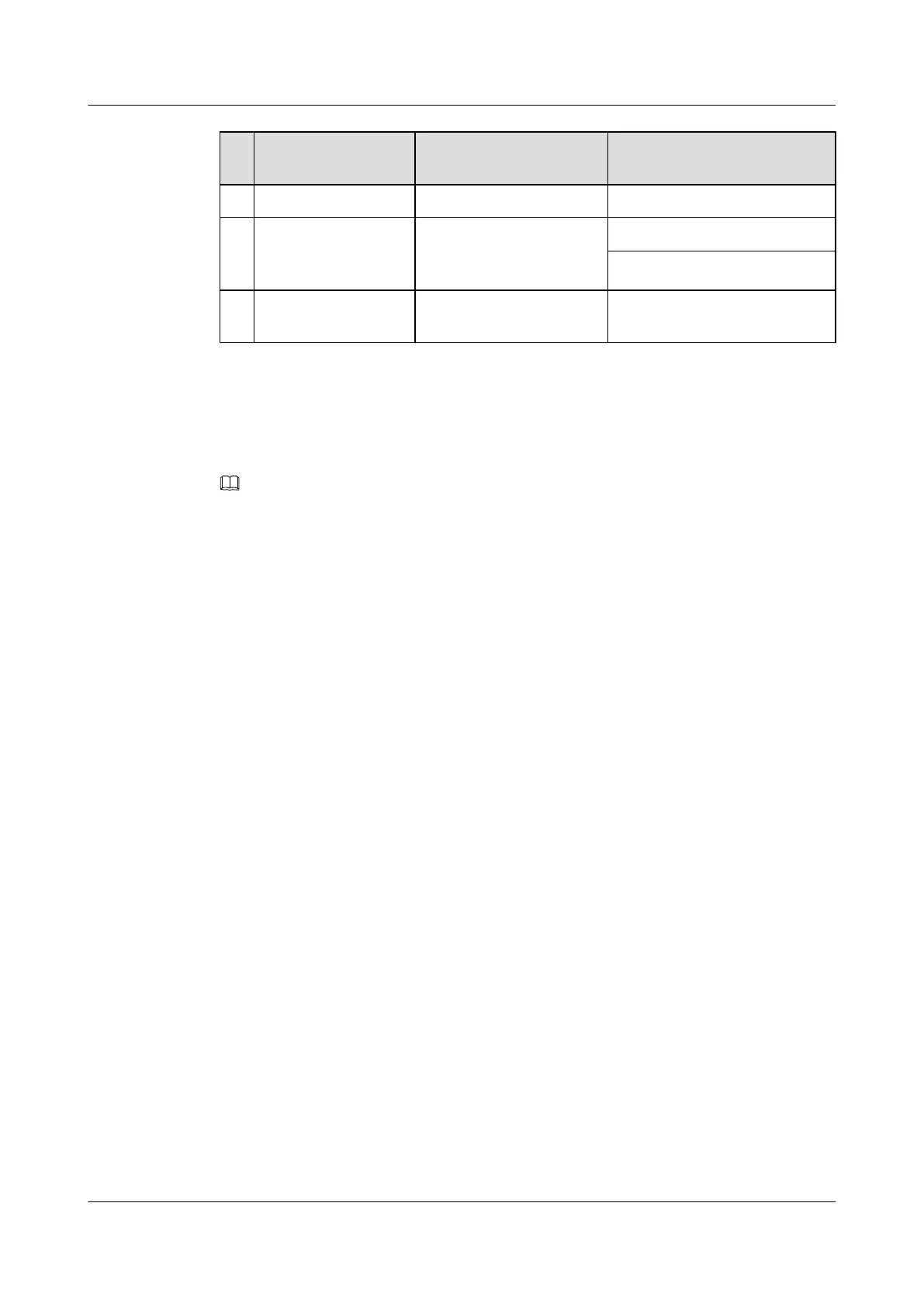
Cable Connector Installation Position
Ground terminal in the IMB03
k Monitoring signal
cable for the AC/DC
power system
RJ-45 connector MON1 port on the UPEU
RS232/RS485
l PDU power cable H4 connector LOAD2 port on the AC/DC
power device
13.5.4 Cable Connections for the IMB03 in the GSM+LTE Scenario
This section describes the cable connections for the IMB03 in the GSM+LTE scenario.
NOTE
In the indoor GL base station, the transmission mode includes co-transmission mode, separate transmission
mode and route backup transmission mode, see Transmission Cable Connections in the Indoor GSM+LTE
Base Station in Co-Transmission Mode, Transmission Cable Connections in the Indoor GSM+LTE Base
Station in Separate Transmission Mode and Transmission Cable Connections in the Indoor GSM+LTE
Base Station in Route Backup Transmission Mode. The following description is based on the separate
transmission.
DBS3900 (Ver.B)
Installation Guide 13 Indoor Scenario (BBU Installed in an IMB03)
Issue 06 (2011-09-15) Huawei Proprietary and Confidential
Copyright © Huawei Technologies Co., Ltd.
473