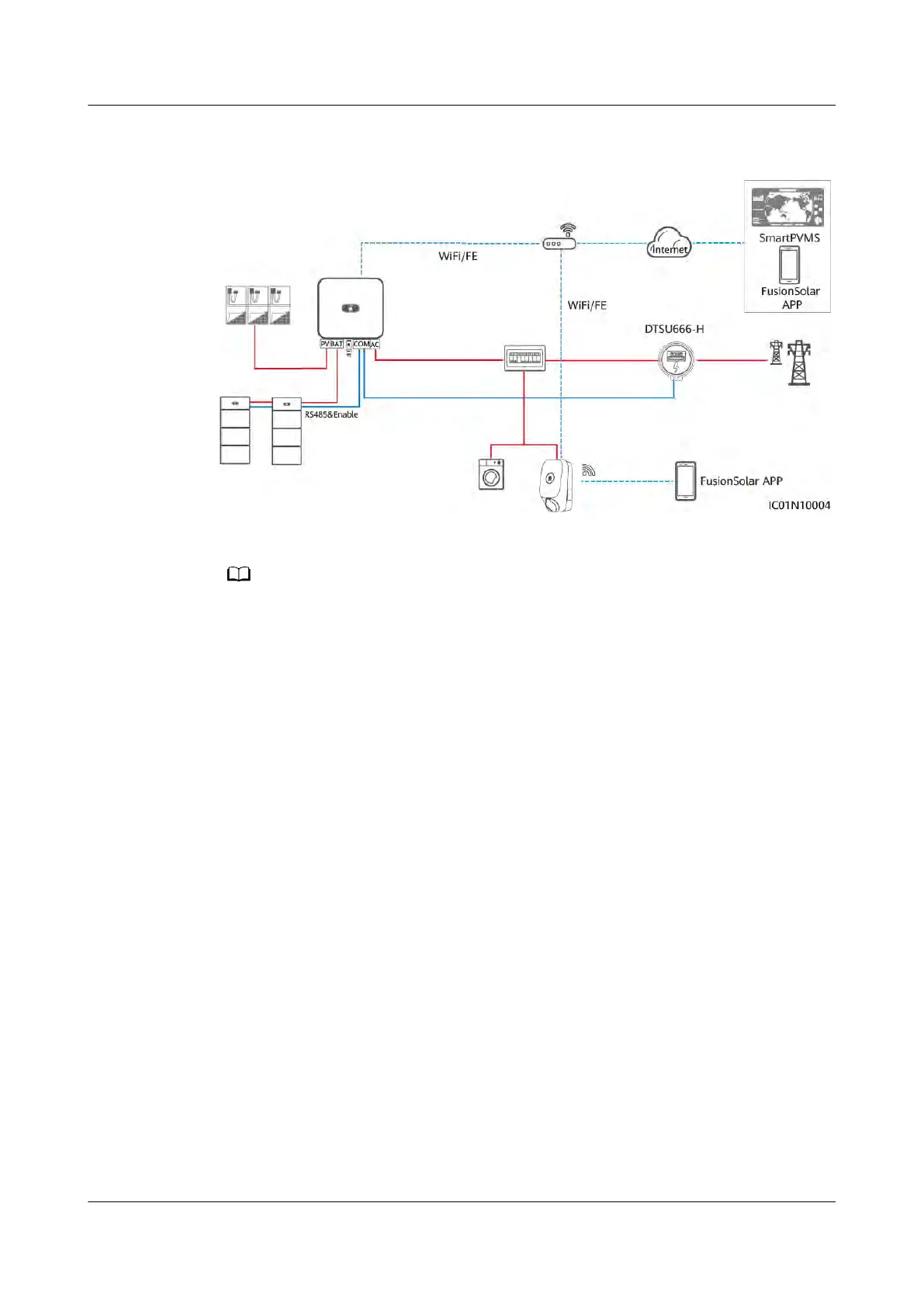
Figure 2-5 PV+Char
ger/PV+ESS+Charger (RS485 meter & FE meter & WLAN/FE
Smart Dongle)
● The WLAN/FE Smart Dongle sends meter data to the charger through Modbus TCP.
When virtual meter net
working is used, set the Modbus TCP parameter of the WLAN/FE
Smart Dongle to Enable (unrestricted). For details, see 4.4.2 PV+Charger/PV+ESS
+Charger.
● If the charger uses virtual meter networking, the WLAN/FE Smart Dongle cannot
connect to a third-party management system using Modbus TCP at the same time.
● If the charger uses virtual meter networking, one router can connect to only one
WLAN/FE Smart Dongle. If two WLAN/FE Smart Dongles are connected to the same
router, communication will be interrupted, resulting in abnormal charger power control.
In this case, you need to connect the WLAN/FE Smart Dongles to two routers
respectively for grid connection.
● The SUN2000-(2KTL-6KTL)-L1 cannot directly connect to the router through WLAN to
implement the virtual meter function. In this case, you need to install the WLAN/FE
Smart Dongle.
PV+Charger/PV+ESS+Charger (RS485 meter & FE meter & non-WLAN/FE
Smart Dongle)
● If the plant cannot use the WLAN/FE Smart Dongle or the SUN2000-
(2KTL-6KTL)-L1 is directly connected to the router, the dual-meter networking
solution can be used. The RS485 meter is used to monitor the grid-connection
point information of the PV+ESS system, and the FE meter is used for
dynamic charging power.
● If the grid-connection point of the plant has power limit requirements, the
power of the grid-connection point must be higher than the minimum startup
power of the charger. Otherwise, the charger cannot start charging in PV
Power Preferred mode and stays waiting to charge.
● If the plant is set to zero feed-in, the charger cannot start charging in PV
Power Preferred mode and stays waiting to charge.
PV+ESS+Charger Solution
User Manual 2 Solution Overview
Issue 02 (2023-01-13) Copyright © Huawei Technologies Co., Ltd. 21