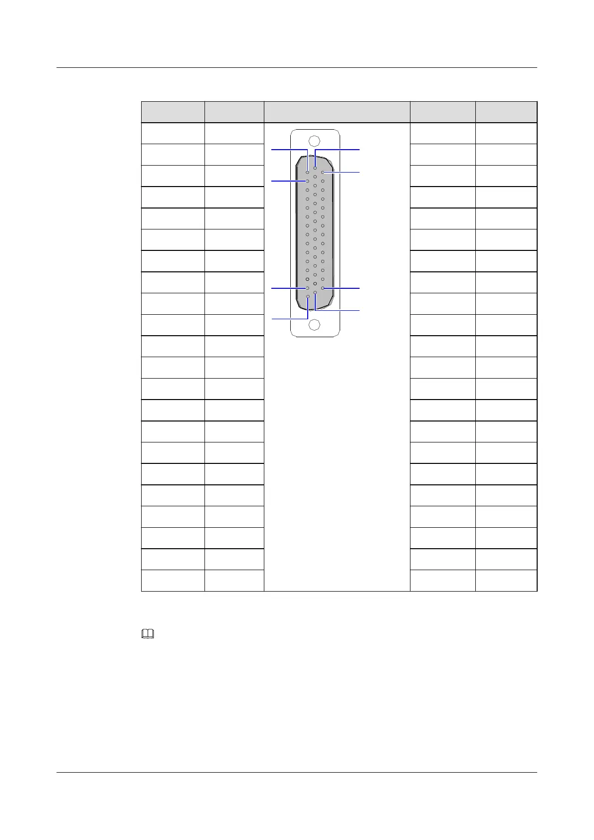
Table 3-76 Pin assignments of the E1 port
Pin Signal Port Pin Signal
30 TT0
8 TR7
15 TR0 37 RR1
44 PGND 22 RT1
29 TT1 7 TT7
14 TR1 36 RR2
43 PGND 21 RT2
28 TT2 6 PGND
13 TR2 35 RR3
42 PGND 20 RT3
27 TT3 5 PGND
12 TR3 34 RR4
41 PGND 19 RT4
26 TT4 4 PGND
11 TR4 33 RR5
40 PGND 18 RT5
25 TT5 3 PGND
10 TR5 32 RR6
39 PGND 17 RT6
24 TT6 2 PGND
9 TR6 31 RR7
38 RR0 16 RT7
23 RT0 1 PGND
NOTE
l In Table 3-76, the first letter "R" or "T" in each cell of the signal column refer to "Receive" or "Transmit"
of E1 signals.
l In Table 3-76, the second letter "R" or "T" in each cell of the signal column refers to "ring" or "tip" of the
75-ohm E1 signal cable, or refers to sign + or – of the 120-ohm E1 signal cable.
Table 3-77 describes the pin assignments of the xDSL port on the front panel of the
H802EDTB board.
SmartAX MA5600T/MA5603T/MA5608T Multi-service
Access Module
Hardware Description
3 Board
Issue 24 (2018-07-30) Huawei Proprietary and Confidential
Copyright © Huawei Technologies Co., Ltd.
511

 Loading...