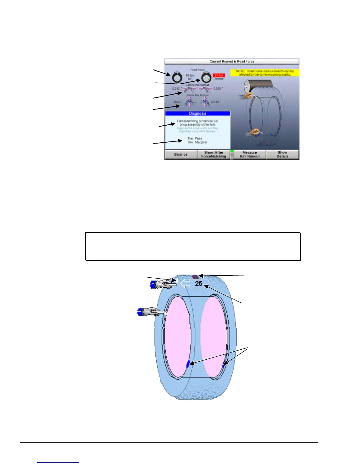
If the wheel assembly can be corrected by using Forcematch®, the diagnosis box will
display “Forcematching procedure will bring assembly within limits” and the
components will be listed as “Pass,” “Marginal,” or “Limit Exceeded.” If non-first
harmonic component limits are exceeded, the “Diagnosis Explanation” popup screen
will automatically appear. Refer to “Diagnosis Explanation Screen,” page 102.
TIRE ROAD FORCE
MEASUREMENT
LATERAL RIM RUNOUT
MEASUREMENT
ASSEMBLY ROAD
FORCE MEASUREMENT
RADIAL RIM RUNOUT
MEASUREMENT
ASSEMBLY DIAGNOSIS
COMPONENT
EVALUATIONS
The “Show After Forcematching” key may be selected to view the estimated road
force that will remain after the Forcematching procedure has been completed.
Forcematch® Procedures
To correct road force by using Forcematch®:
Rotate the tire road force high spot on the wheel to TDC, or with the hood in
the raised position and the servo enabled, press “START.” Mark the tire with
a piece of chalk or a marker at TDC. If desired, mark the tire with the
ForceMatch® Code. Refer to “Using ForceMatch Codes Feature,” page 86.
NOTE: When the wheel is rotated to TDC, the chalk will appear
green on the console display and the tire ForceMatch Code
will appear in the tire tread.
TIRE
FORCE VARIATION
HIGH SPOT MARK
INDIVIDUAL
RIM HIGH SPOTS
TIRE/WHEEL
ASSEMBLY
FORCE VARIATION
HIGH SPOT
TIRE
FORCEMATCH CODE
Rotate the rim low spot on the wheel to TDC, or with the hood in the raised
position and the servo enabled, press “START.” Mark the rim with a piece of
chalk or a marker at TDC. If desired, mark the rim with the ForceMatch Code.
Refer to “Using ForceMatch Codes Feature,” page 86.
84
Road Force® Measurement Procedures GSP9720JLR Wheel Balancer Operation Instructions