Electrical
The GSP9720JLR is manufactured to operate at a specific voltage and amperage
rating.
Make sure that the appropriate electrical supply circuit is of the same voltage and
amperage ratings as marked on the balancer.
WARNING: DO NOT ALTER THE ELECTRICAL PLUG. Plugging the
electrical plug into an unsuitable supply circuit will
damage the equipment.
Make sure that the electrical supply circuit and the appropriate receptacle is installed
with proper grounding.
To prevent the possibility of electrical shock injury or damage to the equipment when
servicing the balancer, power must be disconnected by removing the power cord
from the electrical power outlet.
After servicing, be sure the balancer ON/OFF switch is in the “O” (off) position before
plugging the power cord into the electrical power outlet.
This device is rated as Class A for radiated emissions.
In the event of radio interference, the display read out may flicker - this is normal.
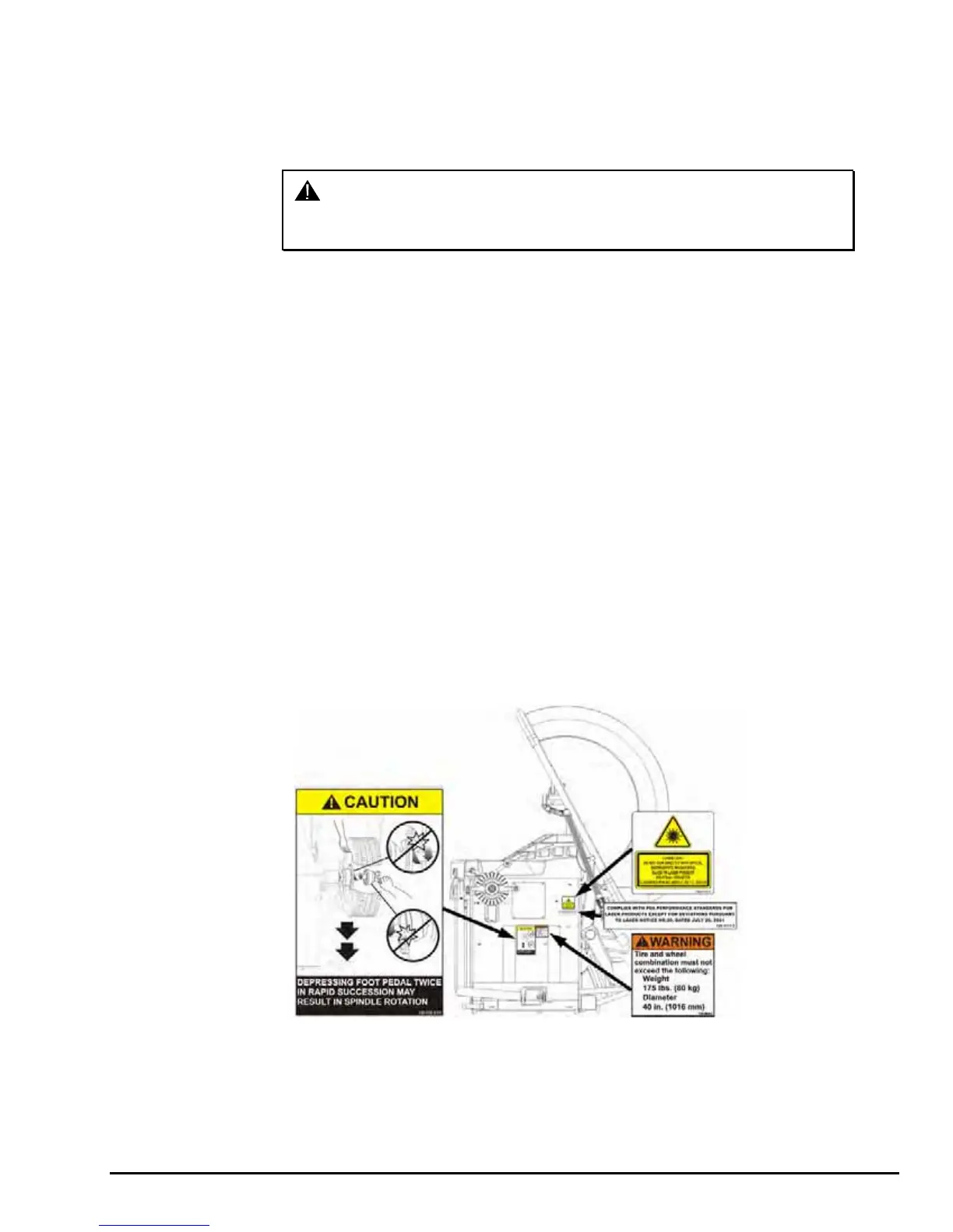
Decal Information and Placement
Right Side View
Decal 128-964-2 gives the maximum wheel diameter and maximum wheel weight for
the GSP9720JLR.
Decal 128-605-2-00 cautions the user that spindle rotation may occur with foot pedal
depression and to keep clear of clamping components during Quick-Thread® shaft
rotation.
Decal 128-116-2 warns the user not to view the laser light with optical instruments.
Decal 128-1117-2 shows the FDA performance standards compliance.
GSP9720JLR Wheel Balancer Operation Instructions Getting Started
3