1 - 16 Machine Components 704-0212-209 VM Series Maintenance and Safety Manual
Electrical Cabinet Layout
Electrical cabinet layout may vary depending upon the machine. See the Parts Listing and
Wiring Diagrams Manual for your machine model.
Electrical Cabinet Components—Mini-ITX Hardware
Platform
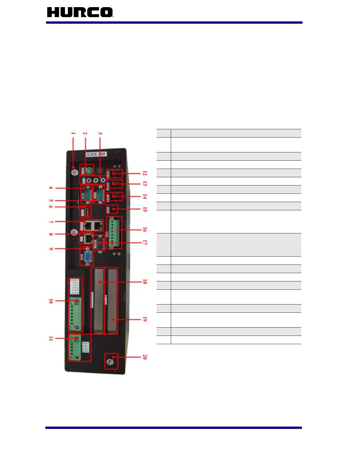
The following section describes the electrical components contained in the Mini-ITX
hardware platform. Shown below is the Mini-ITX Card Rack:
Figure 1–3. Mini-ITX Card Rack
1 SATA Hard Driver Drawer
2
PS/2 Mouse/Keyboard, 6-pin MiniDIN
Connector
3 High Definition Audio Connector
4 COM 1 with DB-9 Connector
5 COM 2 with DB-9 Connector
6 High Retention USB 2.0 Port (USB-0)
7 CANbus Interface RJ-45 x 2
8 Gigabit Ethernet RJ-45
9 Analogue VGA with DB-15 Connector
10
12V Power Output with 6-pin Terminal Block
(Pin Definition from Left to Right:
FG/12V/12V/GND/GND/GND)
11
24V Power Input with 4-pin Terminal Block
(Pin Definition from Left to Right:
24V/24V/GND/GND)
12 USB 2.0 Port x 2 (USB-6/7)
13 USB 2.0 Port x 2 (USB-4/5)
14 USB 2.0 Port x 2 (USB-2/3)
15 USB 2.0 Port x 2 (USB-1)
16
External GPIO Interface with 8-pin Terminal
Block
17 CANbus Interface DSub-9 Pin Connector x 1
18
PCI Express x 16 Slot
(Support PEG Interface Board)
19 PCI Slot for PCI ZMP or PCI STP Board
20 Frame Ground (FGND)
 Loading...