3 - 6 Machine Maintenance 704-0212-209 VM Series Maintenance and Safety Manual
Autolube System
The Autolube system automatically lubricates the slideways, guideways, and ballscrews.
The preset discharge rate is 3.0 cubic centimeters (cc) per pump cycle. Refer to Adjust
Autolube Discharge Rate, on page 3 - 7 for details. The way lube pressure should be set
at 2.9 bar or 42 psi.
Machining centers use a digital timer Autolube system. When servos are On and
adequate pressure is attained, the system cycles on for 30 seconds to send lube oil
through the machine, then cycles off for 15 minutes. The Autolube system is located on
the back of the machine. Open the machine’s rear access door to access the Autolube
system.
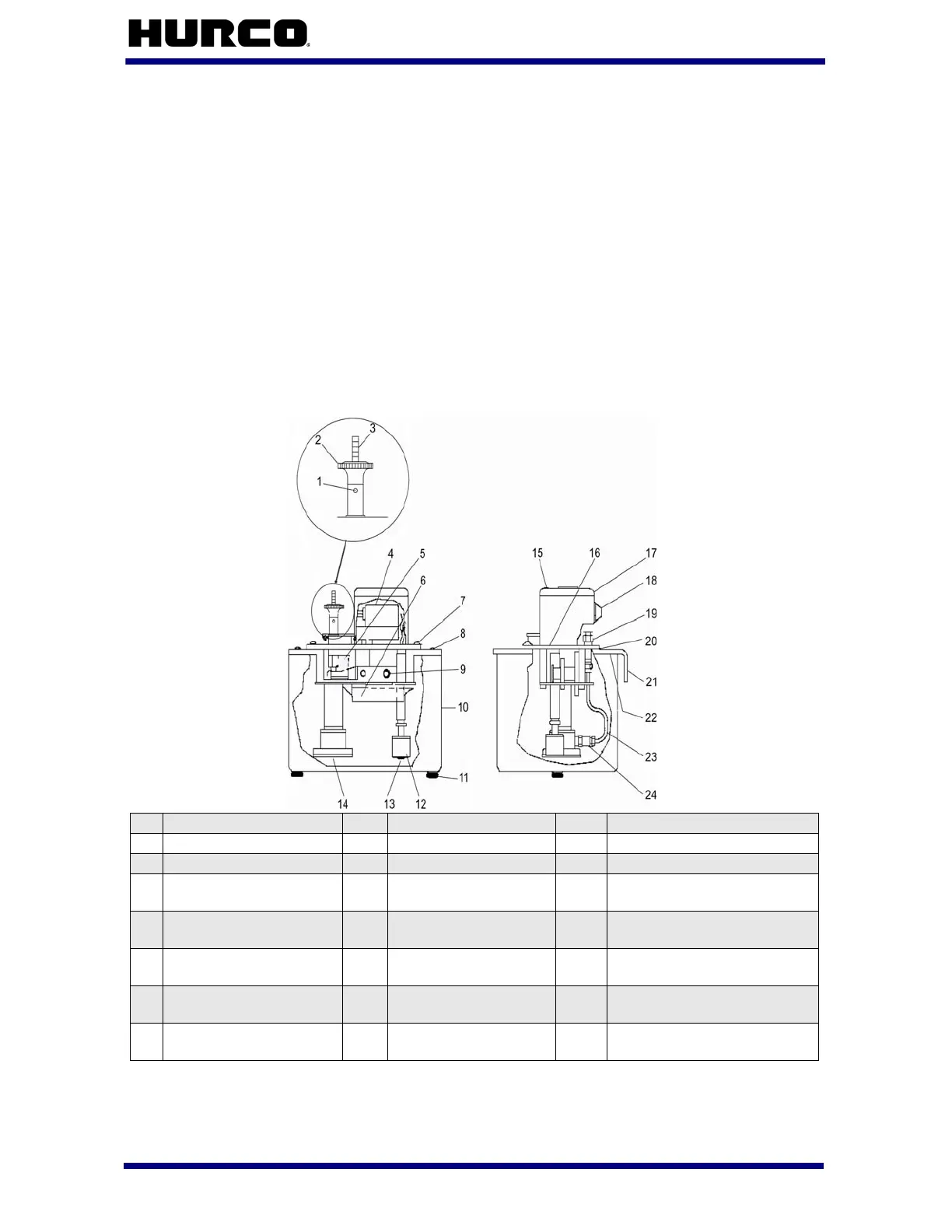
Here is a diagram of a machining center Autolube system:
Figure 3–1. Autolube Pump and Tank Assembly
1
Set screw
9
Retaining ring
17
Motor cover
2
Discharge plunger
10
Reservoir
18
Grommet
3
Indicator rod
11
Screw
19
“Thru” coupling
4
Electric motor
12
Float switch
assembly
20
Reservoir gasket
5
Filter screen
13
O-ring
21
Mounting bracket,
reservoir
6
Reservoir worm and
gear lube
14
Suction filter group
22
Reservoir gasket
7
Screw, cover
mounting
15
Screw, cover
mounting
23
Outlet tube assembly
8
Screw, reservoir
mounting
16
Gasket, motor cover
24
Outlet check valve
assembly
 Loading...