1 - 26 Machine Components 704-0212-209 VM Series Maintenance and Safety Manual
RS-232C Serial Port
The RS-232C serial port can be used to connect peripheral devices to the machine. These
ports may be addressed separately. The standard baud rates are software-selectable. The
ports can be used as an output or input, depending upon the software.
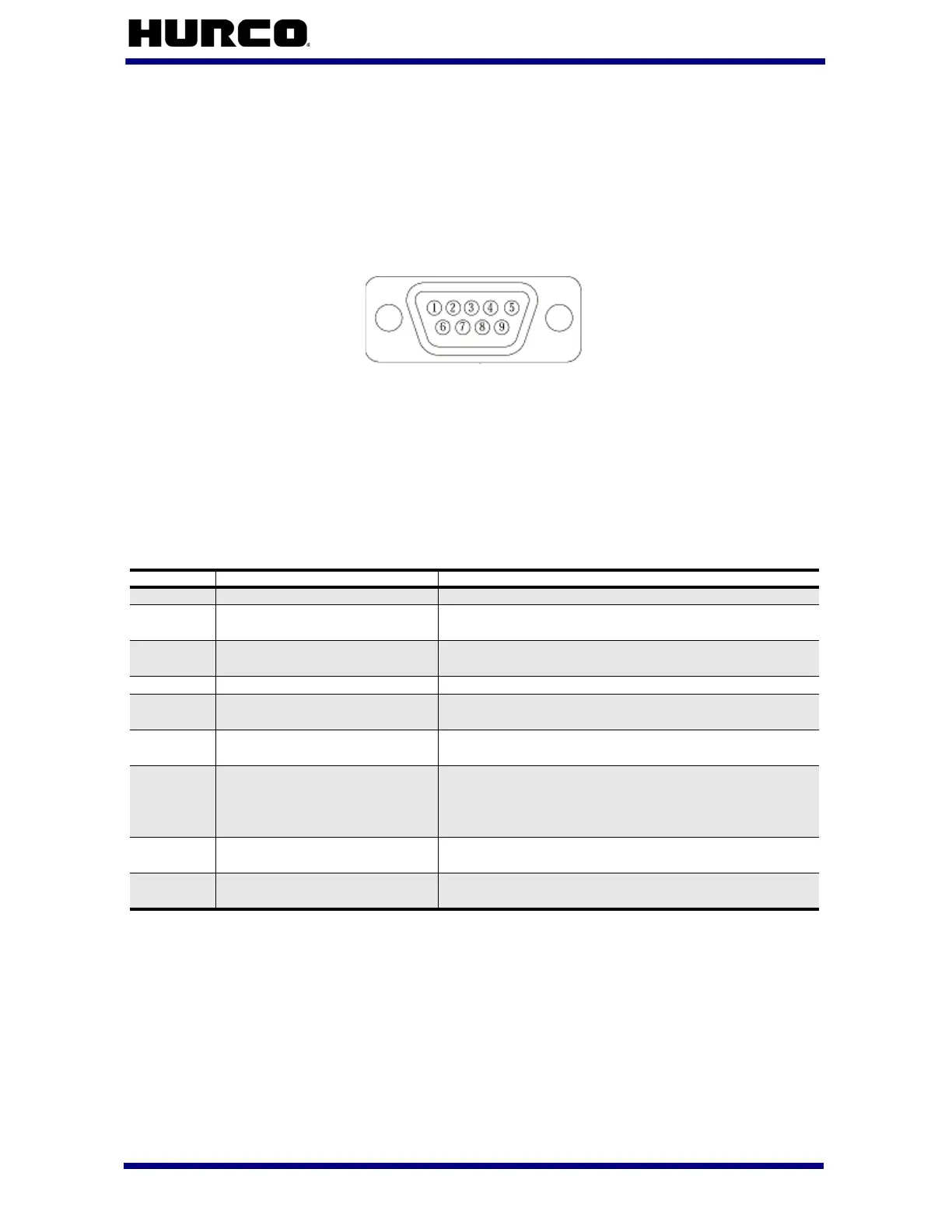
The connector pin designated for the RS-232C signal is shown below:
Figure 1–7. Male 9-Pin D-Type Connector
While the signals present at the serial port conforms to the RS-232C standard, not all
standard RS-232C signals are available. Some peripheral devices may provide RS-232C
control signals that are not available at the port described here. However, such devices
can usually be adapted to the port. In some cases, it may be necessary to add jumpers to
the connector.
Signals available at the serial port are:
Table 1–16. RS-232C Signals Available at Serial Port
To connect a peripheral to the machine, fabricate an adapter cable. If a properly shielded
low capacitance cable is used, cable lengths of up to 100 feet are permissible.
Be certain that you use the correct cabling before connecting the device to the machine.
Consult the peripheral manual to determine whether the peripheral is a Data Terminal
Equipment (DTE) or Data Communication Equipment (DCE) device. The Hurco machine is
a DTE device, and in most cases, so is a personal computer. A printer may be either a
DTE or DCE device.
Pin Signal Name Signal on the Pin
1
Data Carrier Detect (DCD) Not used by the control.
2
Receive Data (RXD) Data received (by machine) in serial format from
peripheral device.
3
Transmit Data (TXD) Data transmitted (by machine) to peripheral
device in serial format.
4
Data Terminal Ready (DTR) Not used by the control.
5
Signal Ground (SG) Line establishing the common ground reference
potential for all interface lines.
6
Data Set Ready (DSR) Signal to notify printer that transmitter is ready
for transmission.
7
Request to Send (RTS) Line used by control to instruct peripheral device
to get ready to receive data. Data can be
transmitted after the Clear-To-Send signal is
received from connected peripheral device.
8
Clear to Send (CTS) Control line used by peripheral device to indicate
that it is ready to receive data from machine.
9
Ring Indicator (RI) Signal indicates modem has received the ring of
an incoming call.
 Loading...