1 Introduction
1 - 1
1 INTRODUCTION
This manual explains the HUST H2N controller's electrical as well as structural
design necessary for connecting the CNC to the machine tool. It also describes the
HUST H2N connection signals including input, output, internal signals, such as S-
bits and C-bits. This manual also describes the functions and the ladder diagram
with corresponding signals. For the functional information of HUST H2N controller,
please refer to the HUST H2N Operation Manual. This manual is intended for users
with some basic electrical and electronic knowledge.
Chapters 1~5 are for those who are interested in electrical connection and Chapters
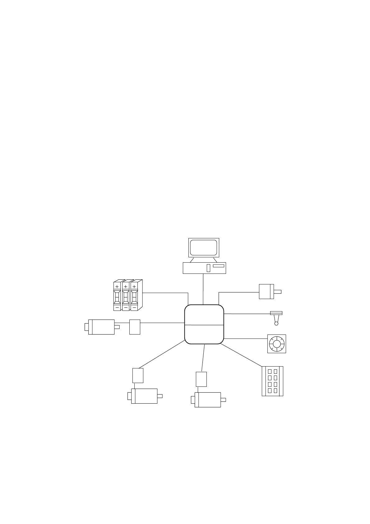
6~8 are for those who are familiar with HUST PLC Editor. Fig 1-1 is a typical
system application of HUST H2N controller to the external devices. The main
features (also see Chap 1 of Operation Manual) of the system are described below.
1. The system can be remotely controlled by PC, HUST CRT screen and PC touch
screen through RS232 interface.
2. The system can handle thumb switch signals through PLC ladder program.
3. The system can control both AC servo and stepping motor.
4. The system provides DI/DO=24/16 points. Also included are connections for
MPG, spindle and Skip sensor.
Fig 1-1 Applications of HUST H2N Controller
PC
Thumb Switch
Spindle Encoder
Skip
1
Driver
AC Servo
1
Driver
AC Servo
Driver
Stepping Motor
MPG
DI/DO
Board
RS232C
HUST H2N
2 Axis CNC
Internal PLC
(ROM/RAM)